Liquid Crystal Video Monitor Model BT-LH1800P Model BT-LH1500P POWER A B S OPTION MENU/ EXIT ENTER BLUE HV ONLY DELAY MULTIFORMAT INPUT SELECT MENU PHASE CHROMA BRIGHT CONTRAST BT- Before attempting to connect, operate or adjust this product, please read these instructions completely.
For Your Safety CAUTION RISK OF ELECTRIC SHOCK DO NOT OPEN CAUTION: TO REDUCE THE RISK OF ELECTRIC SHOCK, DO NOT REMOVE COVER (OR BACK). NO USER-SERVICEABLE PARTS INSIDE. REFER SERVICING TO QUALIFIED SERVICE PERSONNEL. The lightning flash with arrowhead symbol, within an equilateral triangle, is intended to alert the user to the presence of uninsulated dangerous voltage within the products enclosure that may be of sufficient magnitude to constitute a risk of electric shock to persons.
Contents For Your Safety ........................................... 2 Precautions for Use ..................................... 3 Outline ......................................................... 4 Controls and Their Functions ...................... 5 _ Front View ........................................... 5 _ Rear View............................................ 5 How To Use On Screen Menu ..................... 6 _ How To Get On Screen Menu ............. 6 _ MAIN Menu ....................................
Front View 1 2 POWER A B S OPTION MENU/ EXIT ENTER 3 qS BLUE HV ONLY DELAY M INPUT SELECT ! @ MENU # PHASE $ CHROMA BRIGHT % CONTRAST 4 5 6 5
How To Use On Screen Menu How To Get On Screen Menu MARKER [MARKER] R A B S OPTION INPUT SELECT MENU/ EXIT ENTER >MARKER 16:9 MARKER 4:3 MARKER BACK [GPI] PRESET1 PRESET2 BLUE HV ONLY DELAY MENU PHASE CHROMA OFF OFF NORMAL 80% 80% B MARKER menu When MENU/EXIT button is pushed, the main menu appears on the screen.
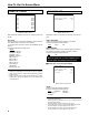
63 VIDEO CONFIG SYSTEM CONFIG [VIDEO CONFIG] >COLOR TEMP SHARPNESS H SHARPNESS V I-P MODE MONO SD ASPECT HD ZOOM D65 3 3 MODE2 OFF 4:3 NORMAL VIDEO CONFIG menu With SYSTEM CONFIG selected, the following menu will appear. BACKLIGHT Used to adjust the brightness of backlight. Set-value (underlined is default value) 7 6 (BT-LH1800) 3 ( B TT f - t L H 1 5 0 0 ) 8 3 3 1 0 T D 0 T c ( Ð ) T j / F 1 3 1 T f 0 . 5 5 5 8 0 T D ( ) T j E T 3 5 4 .
How To Use On Screen Menu REMOTE CONFIG INPUT SELECT [INPUT SELECT] [REMOTE CONFIG] >GPI1 GPI2 GPI3 GPI4 GPI5 GPI6 GPI7 GPI8 UNDEF UNDEF UNDEF UNDEF UNDEF UNDEF UNDEF UNDEF >[LINE A,B/S-VIDEO] NON-STANDARD AUTO OFF REMOTE CONFIG menu INPUT SELECT menu With REMOTE CONFIG selected, the following menu will appear. With INPUT SELECT selected, the following menu will appear. GPI1–GPI8 Used to set the pin assignment of REMOTE control terminal. The settable items are same for each terminal.
How To Use On Screen Menu INPUT SELECT (continued) _ SDI input unit mounted [BT-Y200P] [INPUT SELECT] >[LINE A,B/S-VIDEO] NON-STANDARD [SDI] AUTO OFF AUTO INPUT SELECT (continued) RGB Used to select the format in case of RGB input. Set-value (underlined is default value) AUTO*1) 1080/60I*2) 1080/50I 2) 1035/60I* 720/60P*3) 576/50I 4) 480/60I*4) 480/60P* RGB-SYNC (When RGB is input.) Used to select Ext. Sync/GREEN-On-SYNC.
REMOTE Specifications _ GPI hard specification 8 inputs (refer to D-SUB 9-pin terminal) Pin No. 5 3 4 9 8 2 7 1 6 Contents Pin 1–Pin 4 GPI 1–GPI 4 Pin 5 GND Pin 6–Pin 9 GPI 5–GPI 8 _ ON/OFF operation Each terminal of REMOTE operates its assigned function according to the setting with GND (Pin 5) shorted (ON) or opened (OFF). _ How to assign the function to each terminal The assignment to each terminal can be freely executed by the On Screen Menu. (Refer to “How To Use On Screen Menu”.
Description of MARKER _ Select the MARKER displayed by using the on screen menu. _ MARKER for 16:9 (continued) (Displayed in case of HD, and SD of aspect ratio 16:9) [MARKER] >MARKER 16:9 MARKER 4:3 MARKER BACK [GPI] PRESET1 PRESET2 OFF OFF NORMAL 80% 80% SAFETY ZONE 95% SAFETY ZONE 93% SAFETY ZONE 88% SAFETY ZONE 80% MARKER 16:9 MARKER display selection in case of 16:9 signal input.
Troubleshooting Maintenance Inspection Check and adjust the following points. If it doesn’t work, consult with your dealer. • Operation key does not work. Check that the control lock is not “ON.” # To unlock it, set the CONTROL LOCK in the SYSTEM CONFIG menu to “OFF.” (See page 7.) Maintenance inspections are necessary for the user to use the video equipment safely and to keep the function in good condition at all times through periodical and appropriate maintenance.
Specifications Dimensions: 16-1/4 (W) k 14-15/16 (H) k 3-7/16 (D) inches (412 k 379 k 86 mm) (BT-LH1800) 13-15/16 (W) k 12-3/16 (H) k 3-7/16 (D) inches (353 k 309 k 86 mm) (BT-LH1500) *Depth with option installed is 4-3/8 inches (110mm) for both models. Weight: 18.26 lbs (8.3kg) (main body only, BTLH1800) 13.86 lbs (6.3kg) (main body only, BTLH1500) Operating temp.: i41xF to i95xF (i5xC to i35xC) Storage temp.
PANASONIC BROADCAST & TELEVISION SYSTEMS COMPANY UNIT COMPANY OF MATSUSHITA ELECTRIC CORPORATION OF AMERICA Executive Office: One Panasonic Way 4E-7, Secaucus, NJ 07094 (201) 348-7000 EASTERN ZONE One Panasonic Way 4E-7, Secaucus, NJ 07094 (201) 348-7621 Southeast Region: 1225 Northbrook Parkway, Ste 1-160, Suwanee, GA 30024 (770) 338-6835 Central Region: 1707 N Randall Road E1-C-1, Elgin, IL 60123 (847) 468-5200 WESTERN ZONE: 3330 Cahuenga Blvd W.
Moniteur vidéo à cristaux liquides Modèle BT-LH1800P Modèle BT-LH1500P POWER A B S OPTION MENU/ EXIT ENTER BLUE HV ONLY DELAY MULTIFORMAT INPUT SELECT MENU PHASE CHROMA BRIGHT CONTRAST BT- Il est recommandé de lire attentivement ce manuel avant d’utiliser l’appareil.
Consignes de sécurité ATTENTION RISQUE DE CHOCS ÉLECTRIQUES NE PAS OUVRIR ATTENTION: AFIN DE PRÉVENIR LE RISQUE DE CHOCS ÉLECTRIQUES, NE PAS RETIRER LES VIS. TOUTE RÉPARATION DEVRA ÊTRE CONFIÉE À UN PERSONNEL COMPÉTENT. Le symbole de l’éclair dans un triangle équilatéral indique la présence d’une tension suffisamment élevée pour engendrer un risque de chocs électriques.
Sommaire Consignes de sécurité ................................. 2 Précautions pour l’utilisation ....................... 3 Description sommaire de l’équipement ....... 4 Les Commandes et leurs fonctions ............. 5 _ Vue frontale ......................................... 5 _ Vue arrière .......................................... 5 Comment utiliser les menus sur l’écran ...... 6 _ Comment trouver un menu sur l’écran ................................................. 6 _ Menu MAIN (PRINCIPAL) ............
(4)
Vue frontale 1 2 POWER A B S OPTION MENU/ EXIT ENTER 3 qS BLUE HV ONLY DELAY M INPUT SELECT ! @ MENU # PHASE $ CHROMA BRIGHT % CONTRAST 4 5 6 (5)
Comment utiliser les menus sur l’écran Comment trouver un menu sur l’écran MARQUEUR [MARKER] R A B S INPUT SELECT OPTION MENU/ EXIT ENTER >MARKER 16:9 MARKER 4:3 MARKER BACK [GPI] PRESET1 PRESET2 BLUE HV ONLY DELAY MENU PHASE CHROMA OFF OFF NORMAL 80% 80% B Menu MARKER Lorsque l’on appuie sur la touche MENU/EXIT (MENU/SORTIE), le menu principal apparaît sur l’écran.
Comment utiliser les menus sur l’écran CONFIGURATION VIDÉO [SYSTEM CONFIG] [VIDEO CONFIG] >COLOR TEMP SHARPNESS H SHARPNESS V I-P MODE MONO SD ASPECT HD ZOOM CONFIGURATION DU SYSTÈME D65 3 3 MODE2 OFF 4:3 NORMAL >BACKLIGHT POSITION ERROR MESSAGE STATUS DISPLAY CONTROL LOCK [SET UP] LOAD SAVE 63 CENTER ON CONTINUE OFF FACTORY USER1 Menu VIDEO CONFIG Menu SYSTEM CONFIG Avec VIDEO CONFIG sélectionné, le menu suivant apparaîtra. (Un soulignement représente une valeur implicite.
Comment utiliser les menus sur l’écran CONFIGURATION DE LA TÉLÉCOMMANDE [INPUT SELECT] [REMOTE CONFIG] >GPI1 GPI2 GPI3 GPI4 GPI5 GPI6 GPI7 GPI8 SÉLECTION DE L’ENTRÉE UNDEF UNDEF UNDEF UNDEF UNDEF UNDEF UNDEF UNDEF Menu REMOTE CONFIG Avec REMOTE CONFIG sélectionné, le menu suivant apparaîtra. (Un soulignement représente une valeur implicite.) GPI1–GPI8 Utilisé pour régler l’affectation du contacts du terminal de commande de REMOTE. Les articles réglables sont les mêmes pour chaque terminal.
Comment utiliser les menus sur l’écran SÉLECTION DE L’ENTRÉE (suite) _ Montage de l’unité d’entrée SDI [BT-YA200P] [INPUT SELECT] >[LINE A,B/S-VIDEO] NON-STANDARD [SDI] AUTO OFF AUTO SÉLECTION DE L’ENTRÉE (suite) RGB (rouge/vert/bleu) Utilisé pour sélectionner le format dans le cas d’une entrée de RGB. Réglage de valeur fixe. AUTO*1) 1080/60I*2) 1080/50I 2) 720/60P*3) 576/50I 1035/60I* 480/60I*4) 480/60P*4) RGB-SYNC (Lorsque RGB est introduit.
Spécifications de la TÉLÉCOMMANDE _ Spécifications permanentes de GPI 8 entrées (se référer au terminal à 9 contacts D-SUB) Nx de contacts 5 3 4 9 8 2 7 1 6 Description Contacts 1 – 4 GPI 1–GPI 4 Contacts 5 GND Contacts 6 – 9 GPI 5–GPI 8 _ Fonctionnement ON/OFF (sous tension/hors tension) Chaque terminal de la TÉLÉCOMMANDE fonctionne selon le réglage avec GND (contacts 5) court-circuité (ON) ou ouvert (OFF).
Description des MARQUEURS _ Sélectionner le MARQUEUR affiché en utilisant le menu de l’écran. _ MARQUEUR pour 16:9 (suite) (Affiché dans le cas HD et SD du rapport hauteur/largeur de 16:9.) [MARKER] >MARKER 16:9 MARKER 4:3 MARKER BACK [GPI] PRESET1 PRESET2 OFF OFF NORMAL 80% 80% ZONE DE SÉCURITÉ 95% ZONE DE SÉCURITÉ 93% ZONE DE SÉCURITÉ 88% ZONE DE SÉCURITÉ 80% Menu MARKER (Un soulignement représente une valeur implicite.
Guide de dépannage Inspections pour l’entretien Vérifiez et réglez les points suivants. Si malgré cela, l’appareil ne fonctionne pas, consultez votre revendeur. • Les touches opérationnelles ne fonctionnent pas. Vérifiez que le verrouillage des commandes n’est pas sur “ON” (mise sous tension). # Pour le déverrouillage, réglez CONTROL LOCK dans le menu CONFIGURATION DU SYSTÉME sur “OFF” (mise hors tension). (Voir la page 7.
Fiche technique _ Généralités Alimentation: Consommation: CA 100 V – 240 V, 50 – 60 Hz 0,95 A – 0,40 A (BT-LH1800) 0,66 A – 0,31 A (BT-LH1500) 1 sont des articles de sécurité Dimensions: 412 (W) k 379 (H) k 86 (P) mm (16-1/4 (L) k 14-15/16 (H) k 3-7/16 (D) pouches ) (BT-LH1800) 353 (L) k 309 (H) k 86 (P) mm (13-15/16 (W) k 12-3/16 (H) k 3-7/16 (D) pouches) (BT-LH1500) *La profondeur avec l’installation de chaque option est de 110 mm pour les deux modèles.
Panasonic Canada Inc.