
Datasheet


Digital Fiber Sensor FX-300 SERIES
202
Selection
Guide
Fibers
Ampliers
FX-500
FX-100
FX-300
FX-410
FX-311
FX-301-F7/
FX-301-F
FIBER
SENSORS
LASER
SENSORS
PHOTO-
ELECTRIC
SENSORS
MICRO
PHOTO-
ELECTRIC
SENSORS
AREA
SENSORS
LIGHT
CURTAINS
PRESSURE /
FLOW
SENSORS
INDUCTIVE
PROXIMITY
SENSORS
PARTICULAR
USE
SENSORS
SENSOR
OPTIONS
SIMPLE
WIRE-SAVING
UNITS
WIRE-SAVING
SYSTEMS
MEASURE-
MENT
SENSORS
STATIC
CONTROL
DEVICES
ENDOSCOPE
LASER
MARKERS
PLC /
TERMINALS
HUMAN
MACHINE
INTERFACES
ENERGY
CONSUMPTION
VISUALIZATION
COMPONENTS
FA
COMPONENTS
MACHINE
VISION
SYSTEMS
UV
CURING
SYSTEMS
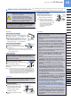
PRECAUTIONS FOR PROPER USE
Refer to General precautions, p.80~ for ber precautions, and to the “PRO mode operation
guide” on our website for details pertaining to operating instructions for the amplier.
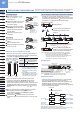
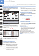
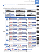
Diagram of functions and settings
The amplier features and settings are generally classied into two main modes; the “NAVI mode” for items and settings that
are frequently recongured, and the “PRO mode” that contains more detailed settings.
NAVI
mode
PRO
mode
Sets output operation either Light-ON,
or Dark-ON.
L-ON / D-ON
L/D
Configures operation of the timer.
Timer
TIMER
Allows various detailed settings to be
configured, such as optical communications,
save / load and other settings.
Pro
PRO
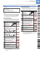
Switches among response times.
Response Time Change
Configures timer operation.
Timer Setting
Sets hysteresis level.
Hysteresis
The “threshold value” can be set by
utilizing either “2-point teaching”, “limit
teaching”, or “full-auto teaching”.
Teaching
TEACH
Allows fine adjustment of the
“threshold value”.
Adjust
ADJ
This indicates normal sensing operation.
Run
RUN
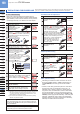
PRO1
PRO2
PRO3
PRO4
PRO5
Shifts the “threshold value” by a
certain percentage increment in
“limit teaching”.
Shift
Permits selection of stability indicator response
levels for changes in the range for lighting up.
[excluding the FX-305(P)]
Stability
Allows selection of different content
to be indicated in the digital display.
Digital Display Setting
Sets the viewing orientation of the
digital display.
Digital Display Inversion
Sets the digital display to turn
ON / OFF.
ECO Mode
Loads configuration setting from the
data bank.
Data Bank Load
Saves configuration setting into the
data bank.
Data Bank Save
Using optical communications, configuration
settings from the main unit are copied to
connected sub units all at once.
Copy
Using optical communication, configuration
settings can be loaded from respective data
banks all at once.
Using optical communication, current
configuration settings can be saved into
respective data banks all at once.
Remote Data Bank Load Remote Data Bank Save
When using optical communication for carrying out
copy / load / save operations all at once, this function
allows optical communication to pass through the unit.
Communication Change
To Permit / Not to Permit
Allows basic configuration information
to be set in a single step, by inputting
a 4-digit code.
Code
Allows fine adjustment of the “threshold
value” to be directly performed during
RUN mode.
Adjust Lock
All settings, except for data bank
information, revert to factory settings.
Reset
The items that can be set are different for output 1 and output 2.
Output 1
Output 2
Changes the light emitting amount
selection setting.
[FX-301(P)(-HS), FX-305(P) only]
Light Emitting Amount Selection
Allows not to save the threshold value, by
teaching via external input in EEPROM.
[FX-301(P), FX-305(P) only]
Backup
Switches the number of units for which
interference prevention switching is enabled.
* FX-305(P) only.
Interference Prevention
Switching
Sets a threshold value for ON /
OFF operation.
Normal Mode
Judges if set two threshold values are within the
required range or not. This can be selected in
1-point / 2-point / 3-point teaching.
Window Comparator Mode
Sensing mode that cancels out slight changes in
light intensity so that only sudden increases in
incident light intensity are sensed.
Rising Differential Mode
PRO6
Trailing Differential Mode
Sensing mode that cancels out slight changes in
light intensity so that only sudden decreases in
incident light intensity are sensed.
Error Output
Output when overcurrent occurs or when
a communication error occurs from
connected incompletely.
Alarm Output
Be used as alarm output when the threshold
value for output 2 is linked to output 1 and
the light amount drops.
Verifies whether optical communications
have been properly established.
(FX-301B/G/H only)
Test
* When the FX-305(P) is in window comparator mode,
the “threshold value” can be set by either “1-point
teaching”, “2-point teaching” or “3-point teaching”.
Available only in FX-305(P)
* The FX-301(P)-HS is not
equipped with a PRO4
setting function.
The FX-301(P)-HS is not
equipped with a PRO4
setting function.
* The 0-ADJ setting function equipped on the FX-301□ and FX-305(P) has been deleted since the production in May 2005.