R Heavy Duty CD Player / Weather Band Receiver with CD Changer Control Heavy Duty CD player/Weather Band Receiver CQ-5500U/5300U Operating Instructions Please read these instructions carefully before using this product and save this manual for future use.
Panasonic welcomes you to our ever growing family of electronic product owners. We know that this product will bring you many hours of enjoyment. Our reputation is built on precise electronic and mechanical engineering, manufactured with carefully selected components and assembled by people who take pride in their work. Once you discover the quality, reliability, and value we have built into this product, you too will be proud to be a member of our family.
Contents Use This Equipment Safely ...................................................................Page 2 Laser Products ......................................................................................Page 4 Part 15 of the FCC Rules ......................................................................Page 4 ❏ Power and Sound Controls ......................................................................5 How to adjust the volume, mute, balance, and tone for best listening ❏ Radio Basics.........
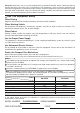
❏ Laser Products (Applies to laser product used in the United States only.) Caution: This product utilizes a laser. Use of controls or adjustments or performance of procedures other than those specified herein may result in hazardous radiation exposure. Laser products: Wave Length 780 nm Laser Power No hazardous radiation is emitted with safety protection.
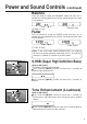
Power and Sound Controls l FEW k BASS/TREB/BAL/FADER 5500U Power If the vehicle is not running yet, turn the key in the ignition until the accessory indicator lights. Press [PWR] to switch on the power. Volume Press the knob to select the volume mode and then turn it clockwise or counterclockwise to adjust the volume level. Volume Level BASS/TREB/BAL/FADER 0 to 40 d Anti-Volume-Blast Circuit At power on, the volume returns to the previous level slowly if the level was at 20 or higher.
Power and Sound Controls (continued) Balance Press the knob to select the BALANCE mode and then turn it clockwise or counterclockwise to shift the sound volume to the right or left speakers. or L (R: Right, L: Left) 1 to 15 Balance Center Fader Press the knob to select the FADER mode and then turn it clockwise or counterclockwise to shift the sound volume to the front or rear speakers.
Power and Sound Controls (continued) Mute l Press [MUTE] to mute the sound completely. FEW k Press and hold 5500U Press [MUTE] again to cancel. Selecting Auxiliary Source (Only for CQ-5500U) Press and hold [MODE] (AUX) for more than 2 seconds to select AUX Input mode. SS/TREB/BAL/FADER Connect the auxiliar y equipment (any other appropriate equipment) to AUX IN Connector. Canceling AUX Input mode Press [MODE] (AUX) to resume the previous mode.
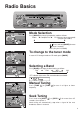
Radio Basics l FEW k BASS/TREB/BAL/FADER 5500U Mode Selection Press [MODE] to change the operation mode as follows. Radio a Compact Disc a CD Changer (when connected) (Only for CQ-5500U) c d SS/TREB/BAL/FADER Press and hold [MODE] for more than 2 seconds. AUX (Only for CQ-5500U) To change to the tuner mode In case of CD changer mode or CD mode, press [MODE]. SS/TREB/BAL/FADER Selecting a Band Press [BAND] to change the band setting as follows.
Radio Basics (continued) Station Preset FM1, FM2 and AM can save maximum 6 stations each in their preset station memories. Caution: To ensure safety, never attempt to preset stations while you are driving. Manual Station Preset ASS/TREB/BAL/FADER Press [BAND] to select a desired band. Use manual or seek tuning to find a station to be stored in the preset memory. Press and hold one of the preset buttons [1] to [6] until the display blinks once.
Tuning in a Weather Band Station Press any of the buttons [1] to [6] to monitor the preset station. The frequency (162) remains unchanged. WB Weather Band Frequency Channel Number Note: The weather band (CH1-6) has been preset. CH7 is selected by pressing [j j] or [i i]. Weather Band Stations National Weather Radio Broadcasts from over 380 locations throughout the U.S. on seven VHF/FM frequencies.
Compact Disc Player Basics Caution: Only 12 cm CD is available for this unit. l FEW k BASS/TREB/BAL/FADER 5500U To play CD Insert the disc and play starts automatically. "LOAD" will be displayed until the disc is loaded. Play starts from the first track. 5500U Caution: Do not use irregularly-shaped CD. Failure to observe this may cause malfunction. Note: While the disc is in the deck, " " indicator lights.
Repeating a Track Press [5](RPT: REPEAT) to repeat the current selection. REPEAT Press [5](RPT: REPEAT) again to cancel. Random Selection Press [6](RDM: RANDOM). A random selection of music is played from all available tracks. RANDOM Press [6](RDM: RANDOM) again to cancel. Scanning Track Press [4](CD SCAN). The display will blink and the first 10 seconds of each track on the disc play in sequence. Disc Press [4](CD SCAN) again to cancel.
CD Changer Basics (Only for CQ-5500U) Note: CD changer functions are designed for an optional CD changer unit. l FEW k BASS/TREB/BAL/FADER 5500U Starting the CD Changer Once the CD changer has been connected, press [MODE] to change to the CD changer mode. When a disc magazine is inserted, CD play starts automatically. SS/TREB/BAL/FADER Play Disc Track Time Number Number Selecting a Disc Press [1] (i DISC) or [2] (DISC j) to select a disc in descending or ascending order.
Track Repeat Press [5](RPT: REPEAT) to repeat the current selection. "REPEAT" indicator lights. REPEAT Press [5](RPT: REPEAT) again to cancel. Random Selection Press [6](RDM: RANDOM). A random selection of music is played from all available discs/tracks. RANDOM Press [6](RDM: RANDOM) again to cancel. Note: The Random mode will stop and the disc select function will operate once the [1] (i DISC) or [2] (DISC j) is pressed. Scanning Track Press [4](CD SCAN).
Clock Basics (The clock system is 12-hours.) l FEW k BASS/TREB/BAL/FADER 5500U Initial Time Press and hold d Press and hold [CLK] to set time. Display blinks, and the time setting mode is activated. Press [i i] to set the hour. Press [j j] to set the minute. (Hold [i i] or [j j] to change numbers rapidly.) Once the time has been set, release [CLK]. Note: When the clock is not set yet, "SET" is displayed.
Alarm Time Setting Press and hold d Press and hold [ALM] to set alarm time. Display blinks, and the alarm time setting mode is activated. Press [i i] to set the hour. Press [j j] to set the minute. (Hold [i i] or [j j] to change numbers rapidly.) When you have set the alarm time, release [ALM]. Note: When the alarm is not set yet, "AM 12:00" is displayed. l FEW k 5500U or l FEW k 5500U Alarm Time Reset To reset the alarm time, repeat steps and above.
Temperature Reading (Only for CQ-5500U) Press and hold To read the temperatare outside the vehicle, press and hold the knob [SEL] for more than 2 seconds. The current temperature in Fahrenheit appears on the display. BASS/TREB/BAL/FADER Press and hold the knob [SEL] for more than 2 seconds again to cancel the temperature reading mode. Press and release Press and release the knob [SEL] to shift the temperature display to the current operating mode.
Installation Guide WARNING This installation information is designed for experienced installers and is not intended for non-technical individuals. It does not contain warnings or cautions of potential dangers in attempting to install this product. Any attempt to install this product in a motor vehicle by anyone other than qualified installer could cause damage to the electrical system and could result in serious personal injury or death. ❏ Overview This equipment should be installed by a professional.
Installation Guide (continued) ❏ Required Tools You'll need a screwdriver, a 1.5 volt AA battery and the following: 12 V DC ELECTRICAL SIDE-CUT TEST BULB TAPE PLIERS Cut the connector wires one at a time from the plug (leaving the leads as long as possible) so that you can work with individual leads. Turn the ignition on to the accessory position, and ground one lead of the test bulb to the chassis. ❏ Dashboard Specifications THICKNESS MIN. 3/16" (4.75 mm) MAX. 7/32" (5.
A handy way to identify the speaker leads and the speaker they connect with is to test the leads using a 1.5 volt AA battery as follows. Hold one lead against one pole of the battery and stroke the other lead across the other pole. You will hear a scraping sound in a speaker if you are holding a speaker lead. If not, keep testing different lead combinations until you have located all the speaker leads. When you label them, include the speaker location for each. Speakers Connect the speaker wires.
Installation Guide (continued) Battery Connect the yellow battery lead to the correct radio wire or to the battery fuse port on the fuse block. Antenna Connect the antenna by plugging the antenna lead into the antenna receptacle. Equipment Connect any optional equipment such as amplifier, according to the instructions furnished with the equipment. Keep about 12 inches (30 cm) of distance between the speaker cords/amplifier unit and the antenna/antenna extension cord.
❏ Installation Procedures When bending the mounting tab of the mounting collar with a screwdriver, be careful not to injure your hands and fingers. We strongly recommend you to wear gloves for installation work to protect yourself from injuries. Note: Disconnect the cable from the negative (–) battery terminal. 1. Secure the Mounting Collar . Insert Mounting Collar into the vehicle's dashboard, and bend mounting tabs out with a screwdriver. Mounting Tab Dashboard 1 Mounting Collar Screwdriver 2.
Installation Guide (continued) ■ Using the Rear Support Strap ■ Using the Rubber Cushion (option) (If there is an existing Rear Support Bracket on the fire wall of the vehicle.) Cover Mounting Bolt on the rear of the unit with Rubber Cushion (option), and mount it into the existing Rear Support Bracket. Rear Support Bracket (existing on the vehicle) Rubber Cushion (option) Mounting Bolt Mounting Collar 3. After installation reconnect the negative (–) battery terminal.
To remove the unit from the vehicle's dashboard Insert each Removal Tool and pull. Removal Tool (U-shaped) Note: Do not lose Removal Tool. They will be needed to remove the unit from the vehicle's dashboard.
Electrical Connections (Only for CQ-5500U) Cautions: This product is designed to operate with a 12-volt negative ground battery system. To prevent damage to the unit, be sure to follow the connection diagram below. Remove the covering of the leads approx. 5 mm long from their end before connecting. Do not insert the power connector into the unit until the wiring is completed. Be sure to insulate any exposed wires from a possible short-circuit from the vehicle chassis.
Electrical Connections (continued) (Only for CQ-5300U) Cautions: This product is designed to operate with a 12-volt negative ground battery system. To prevent damage to the unit, be sure to follow the connection diagram below. Remove the covering of the leads approx. 5 mm long from their end before connecting. Do not insert the power connector into the unit until the wiring is completed. Be sure to insulate any exposed wires from a possible short-circuit from the vehicle chassis.
Troubleshooting Error Display Messages ❏ Maintenance Your product is designed and manufactured to ensure a minimum of maintenance. Use a soft cloth for routine exterior cleaning. Never use benzine, thinner, or other solvent. E1 Appears on the display when the compact disc is dirty or inverted. The disc is ejected automatically. But, the disc may be ejected automatically, even if this error message is not displayed. E2 Appears on the display when compact disc is scratched.
Troubleshooting (continued) ❏ Troubleshooting Tips PROBLEM POSSIBLE CAUSE PROBABLE SOLUTION Unit does not turn on. Dead vehicle battery Ignition or ACC is not on. Bad power line connection Fuse burned out Charge vehicle battery. Turn ignition to On or ACC. Check connections. Replace fuse.(consult your dealer) Radio has static. Antenna not hooked up Close to high power lines Hook up antenna. Move away from high power lines.
Special Notes Notes on Compact Discs ONLY USE DISCS CARRYING LABEL SHOWN ON THE RIGHT Label Dirt, dust, scratches and bending of disc will cause misoperation. Handle discs with care. Do not place stickers or make scratches on disc. Do not bend discs. Disc should always be kept in the case when not in use to prevent from damaging. Do not place discs in the following places: 1. Direct sunlight 2. Dirty, dusty and damp areas 3. Near vehicle heaters 4.
Specifications General Power Supply Maximum Power Output Power Output Tone Action Current Consumption Speaker Impedance Dimensions (W × H × D) Weight : 12 V DC (11V-16V) Test Voltage 14.4V, Negative ground : 37 W × 4 channels at 400 Hz, Volume Control maximum : 18 W per channel into 4 ohms, 40 to 30,000Hz at 3% THD. : Bass; ± 12 dB at 100 Hz Treble; ± 12 dB at 10 kHz : Less than 2.5 A (CD mode, 0.5 W 4-speaker) : 4 Ω (4-8 Ω acceptable) : 7" × 1-15/16" × 5-7/8" (178 × 50 × 150 mm) : 3 lbs. 3 oz. (1.
Panasonic Consumer Electronics Company, Division of Matsushita Electric Corporation of America One Panasonic Way, Secaucus, New Jersey 07094 YFM284C332ZA TAMACO0200-0 Printed in Taiwan