CD Player/Receiver with CD Changer Control CQ-DFX202N REMOTE AUTO·P OPEN MONO/LOC VOL BAND PTY PWR TUNE SEL TRACK SOURCE CD RECEIVER WITH CHANGER CONTROL LOUD DISP 1 EON EPTY ECT RANDOM DISC CT 2 3 R 4 SCAN 5 REPEAT SCAN REP 6 REG AF SUB·W TA CQ-DFX202N Operating Instructions Bedienungsanleitung Manuel d’instructions Gebruiksaanwijzing Bruksanvisning Manuale di istruzioni Manual de Instrucciones ¡Please read these instructions carefully before using this product and keep this
Label Indications and Their Locations Warnetiketten und deren Anbringungsort Indications portées les étiquettes et emplacement Aanduiding van de labels en hun plaats Varningsskyltarna, och deras placering Indicazioni delle etichette e le loro posizioni Indicaciones de las etiquetas y su ubicación VORSICHT! UNSICHTBARE LASERSTRAHLUNG! WENN ABDECKUNG GEÖFFNET IST, NICHT DEM LASERSTRAHL AUSSETZEN.
RDS (Radio Data System) .................................. 10 Clock Set ............................................................. 13 CD Player and CD Changer ............................... 14 Installation........................................................... 16 Anti-Theft System ............................................... 19 Electrical Connections ....................................... 20 Speaker Connections ......................................... 22 Fuse ..................................
Precautions (ISO Connector) ¡The pin arrangement of the power connector conforms to ISO standard. ¡The pin arrangement of ISO connectors in some cars may differ from the ISO standard. ¡Please check that the pin arrangement of the connector in your car conforms to ISO standard. ¡For car types A and B, change the wiring of the red and yellow leads as shown at right. ¡After connection, insulate the portions marked (C) with insulating tape.
ISO Standard ISO ¡IGN or ACC switched 12V supply ¡Zündschalter (ACC/IGN) ¡Sélecteur ACC/IGN ¡ACC/IGN schakelaar ¡tändningsomkopplare ¡Interruttore ACC/IGN ¡Llave ACC/IGN ¡+12 V Battery (Permanent supply) ¡+12 V-Batterie ¡Batterie +12 V ¡+12 V accu ¡+12 V batteri ¡Batteria +12 V ¡+12 V Batería A A7 (Red) (Rot) (Rouge) (Rood) (Röd) (Rosso) (Rojo) ACC BATTERY 15A A4 A4 (Yellow) C (Gelb) (Jaune) (Geel) (Gul) (Giallo) (Amarillo) (Yellow) (Gelb) (Jaune) (Geel) (Gul) (Giallo) (Amarillo) Car Type A ¡+12
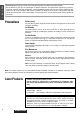
E N G L I S H Panasonic welcomes you to their constantly growing family of electronic products owners. We endeavor to give you the advantages of precise electronic and mechanical engineering, manufactured with carefully selected components, and assembled by people who are proud of the reputation their work has built for our company.
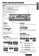
Power and Sound Controls E N G L I S H Power Turn the key in the ignition until the accessory indicator lights. Power on : Press [SOURCE] (PWR). Power off : Press [SOURCE] (PWR) again and hold. The panel removal alarm sounds. (a Page 19) Note: When the power is switched on for the first time, a demonstration message appears on the display. To cancel this display, press [DISP]. Remote control sensor for an optional remote control.
E N G L I S H Radio Basics q Mode Selection (SOURCE) Press [SOURCE] to change to the radio mode. 3 Radio CD Player (When a CD is inserted) CD Changer Control (When a CD changer is connected) CQ-DFX202N REMOTE AUTO·P OPEN MONO/LOC VOL ST BAND PTY PWR TUNE SEL TRACK SOURCE CD RECEIVER WITH CHANGER CONTROL LOUD DISP 1 EON EPTY ECT RANDOM DISC CT 2 3 R 4 SCAN 5 SCAN REPEAT REP 6 REG TA AF SUB·W w Band Press [BAND] to change the bands.
Preset Station Setting Caution: To ensure safety, never attempt to preset stations while you are driving. Up to 6 stations each can be saved in the FM1, FM2, FM3 and AM (LW/MW) preset station memories. E N G L I S H 4 q Band Select a band.
E N G L I S H 5 RDS (Radio Data System) RDS Basics The following functions are available when receiving RDS stations. PS Display CT Service AF (Program Service name) (Clock Time) (Alternative Frequency list) The name of station is displayed instead of the frequency. When receiving an RDS station, the CT (Clock Time) service automatically adjusts the time. "NO CT" is displayed in areas where CT service is not available.
E N G L I S H Traffic Announcements Some RDS FM stations periodically provide traffic information. TP TA (Traffic Program Identification) (Traffic Announcements Identification) Broadcasting of traffic information Radio announcements on traffic conditions TA Mode 6 TP seek tuning. TA on Press [TA] to switch TA mode on and off.
E N G L I S H 7 RDS (Radio Data System) (continued) PTY Reception (Program Type) RDS FM stations provide a program type identification signal. Example: news, rock, classical music, etc. PTY Mode Press [PTY] to switch PTY display mode on or off. PTY on ST When there is no corresponding program type, “NO PTY” is displayed.
Clock Set E N G L I S H When RDS CT service is not available, set the clock as follows. PTY Preset 8 BAND Program types are stored in the memory under preset buttons from [1] to [6] shown in the table below. o. et N g s Pre Pro 1 News 2 Speech 3 Sport 4 Pop. Music 5 6 ype T ram y ails pla Dis Det NEWS AFFAIRS / INFO EDUCATE / DRAMA CULTURES / SCIENCE VARIED / WEATHER FINANCE / CHILDREN SOCIAL A / RELIGION PHONE IN / TRAVEL LEISURE / DOCUMENT SPORT POP.
E N G L I S H 9 CD Player and CD Changer Disc Insert and Playback q Open the front panel. w Insert a disc. e Close the front panel manually. Play back will start automatically. Open Eject Listening to a CD Mode Selection Press [SOURCE] to change to the CD or CD changer mode. Label side Radio OPEN MONO/LOC PTY PWR CD Player (When a CD is inserted) SOURCE Caution: Only 12cm CD, CD-DA data recorded CD-R and CD-RW discs are available for this unit.
Note: The CD Changer functions are designed for an optional CD changer unit.
E N G L I S H 11 Installation Preparation ¡Before installation, check the radio operation with antenna and speakers. ¡Disconnect the cable from the negative (–) battery terminal (see caution below). ¡Unit should be installed in a horizontal position with the front end up at a convenient angle, but not more than 30°. ¡We strongly recommend that you wear gloves for installation work to protect yourself from injuries. First complete the electrical connections, and then check them for correctness.
¡When bending the mounting tab of the mounting collar with a screwdriver, be careful not to injure your hands and fingers. 1 Insert Mounting Collar q into the dashboard, and bend the mounting tabs out with a screwdriver. Q’ty E N G L I S H 12 Supplied Hardware No.
E N G L I S H 13 Installation (continued) To Remove the Unit q Remove the removable face plate. Open Contact w Push q Open (a) Open the face plate. OPEN MONO/LOC PTY e Pull out PWR SOURCE (b) Push the face plate to either the right or left, then pull it out toward you. w Remove the trim plate t with a screwdriver. tTrim Plate Screwdriver 1 2 e Pull out the unit while pushing down the lock lever with a screwdriver. Lock Lever Screwdriver r Remove the unit pulling with both hands.
Anti-Theft System E N G L I S H This unit is equipped with a removable face plate. Removing this face plate makes the radio totally inoperable. r Removable Face Plate Case Place Removable Face Plate into Case 14 q Switch off the power of the unit. w Remove the removable face plate. (a Page 18) e Gently press the bottom of the case and open the cover. Place the face plate into the case and take it with you when you leave the car. Cautions: ¡This face plate is not water-proof.
E N G L I S H Electrical Connections Cable Wiring Diagram Example : Connection with CD changer CX-DP88N (Option) 15 CD Changer CX-DP88N Extension Cord (DIN/BATT/RCA/GND) (Black) (Yellow) Fuse (3A) Changer Control DIN Cord (L)(White) (R)(Red) RCA Cord Antenna CD Changer Control Connector CD Receiver CQ-DFX202N y ISO Antenna Adapter (if needed) L(White) R(Red) Preamp Out Connector (Rear) CD Changer Input Connector Rear Left + Rear Left – Front Left + Front Left – Front Right + Front Right – Re
Ground Lead To a clean, bare metallic part of the car chassis Battery Lead To the car battery, continuous +12V DC Cautions: ¡Check the connectors provided on your car (see note on page 4 and 5) before connecting the system. ¡This unit is designed for use in a car having a 12-volt negative ground battery system. ¡To prevent damage to the unit, be sure to follow the connection diagram. ¡Strip about 5 mm of the lead ends for connection (only nonISO connector cords).
E N G L I S H Speaker Connections Caution: Please follow the instructions given below. Failure to do so will cause damage to the unit and speakers. 17 L + - R+ - (White) + - (White w/black stripe) (Gray) + - (Gray w/black stripe) ¡Use ungrounded speaker only. ¡The maximum speaker output should be 45 W or more. (If used with the optional power amplifier, the speaker output should be higher than the maximum amplifier output.) ¡The speaker impedance should be 4 - 8 Ω.
Specifications General FM Stereo Radio Power Supply Frequency Range Usable Sensitivity Stereo Separation : DC 12 V (11 V - 16 V), Test Voltage 14.4 V, Negative Ground Tone Controls : Bass; ±12 dB at 100 Hz Treble; ±12 dB at 10 kHz Current Consumption : Less than 2.5 A (CD mode, 0.
Matsushita Electric Industrial Co., Ltd. Central P.O. Box 288, Osaka 542-8588, Japan Dalian Matsushita Communication Industrial Co., Ltd. Daxinzhaizi, Ganjingzi District, Dalian, China P.C.