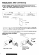
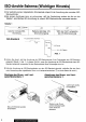
Precautions (ISO Connector) * Wiring for the power connector conforms to the arrangement of standard ISO connectors. # In case of some car types, the arrangement of connector may differ from the standard ISO as shown in Table 1, even though ISO connectors are adapted. Table Battery “IGN” or “ACC” Car for standard ISO (permanent 12 V supply) (switched 12 V supply) SO-Standard A7: ACHING Switch GT Cav Ground =| —— Ad: +12Y Battery Fig.
Panasonic welcomes you to their constantly growing family of electronic products owners. We endeavor to give you the advantages of precise electronic and mechanical engineering, manufactured with carefully selected components, and assembled by people who are proud of the reputation their work has | built for our company.
ISO-Anstrahle Schema (Wichtiger Hinweis) ® Die Verdrahtung des mitgelieferten Stromkabels entspricht der Anordnung der normalen Eisosteckverbinder, ® Bei einigen Autotypen kann es vorkommen, dal die Verdrahtung anders als die aus der Tabelle 1 ersichtlichen SO-Anordnung ist, obwohl! ISO-Steckverbinder verwendet werden. Tabelle 1 Se Abb. 1, Stift Nr.
Précautions (Connecteur ISO) ® Le ciblage pour le cordon d'alimentation prévu en accessoire se conforme a I'alignement des connecteurs standard ISO. ® Pour certains types de véhicules, une partie de ciblage peut différer de l'alignement standard 1SO comme Endigue le Tableau 1, mémé si les connecteurs 1SO sont adoptés.
Panasonic vous souhaite la bienvenue pimai la famille toujours croissante des possesseurs de nos appareils électroniques. Nous avons fait de notre mieux pour vous apporter les avantages de la précision mécanique et électronique de pointe, étant donné que Appareil a 61 composé avec des pinces soigneusement choisies et montées par des gens qui tans fiers de la renommée de leur Société que leur travail consciencieux lui a value.
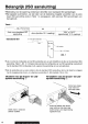
Belangrijk (ISO aansluiting) ® Bedrading voor de spanning voldoet aan gerichtlijn voor standaard ISO aansluitingen. ® Bij bepaalde automerken, zal een deel van de bedrading mogelijk verschillen van de standaard ISO aansluiting zoals in Tabel 1 is aangegeven, zelfs wanneer ISO aansluitingen worden gebruikt. Tabel 1 TT Afb. 1 Pijnnummer Ad A7 Auto voor standaard 150 . . "IGN" of "ACC" aansluiting Accu tkontinu 12 V voeding) {geschakeld 12 V voeding) Standaard 1SO 27: ACCHGN Schaakstar Aarding 12V Abou Afb.
— N Panasonic heet u van harte welkom bij de nog steeds groeiende familie van eigenaars van onze olekironische producten, Panasonic streeft maar om u de voordelen van nauwkeurige slekironische en mechanische technologie te bieden, door gebruik te maken van zorgvuldig geselekieerde componenten. Hiernaast werd dit product gefabriceerd door technici die trots zijn op de reputatie die hun werk voor onze firma opgebouwd heeft.
Precauzioni (Connettore ISO) ® |i cablaggio per il cavo di alimentazione accessoria & conforme all'allineamento dei collegamenti ISO standard. # Per alcuni tipi di auto, parti del cablaggio possono differire dall'allineamento ISO standard mostrato nella tabella 1, anche se sono impiegati connettori ISO. Tabella 1 CS — Terminatole in Fig.
~~ leda nostra famiglia. Passionale Vi da il benvenuto nella famiglia in costante aumento dei proprietari dei suol prodotti elettronici. Noi cerchiamo sempre di offrirvi i vantaggi di una tecnica elettronica e di una meccanica perfetta nel nostri prodotti fabbricati con componenti: altamente selezionati e lavorati da persone che godono di piena filugello presse la nostra compagnia.
Precauciones (Conector ISO) ® El alambrado del cordón de alimentación estad de acuerdo con la alineación de los conectores normales de la ISO. © Para algunos tipos de carros, parte del alambrado puede ser diferente de la alineación ISO normal como se muestra en la Tabla 1, aunque se adopten los conectores 150.
Panhispánico le da la bienvenida a la familia constantemente en aumento de poseedores de productos ele: céntricos. Nos esforzamos en proporcionare las ventajas de fa ingeniera mecánica y electrónica de precisión, de una fabricación con componentes cuidadosamente seleccionados, y de un montaje realizado por personas orgullosas de la reputación que su trabajo ha cimentado para nuestra empresa.
Power and Sound Controls Turn the key in the ignition until the accessory indicator fights. Press PWR to switch on the power. Press PWR again to switch off the power. Note: When the PWR is switched on for the first ime, a demonstration message appears on the display. To cancel this display, press Volume Press VOL or VOL to increases or decrease the volume. — Volume Level Oto 40 Press VOL A or VOL\/ for more than 0.5 second to sequentially change numeric levels on the display.
Bass and Treble Press SEL to change to the BASS (TREBLE) mode. Press VOL A or VOL VV fo increase or decrease the bassinet response. ~1210 +12 ~1210 +12 nM Zr-rOzm Balance Press SEL to change to the BALANCE mode. Press VOL A or VOL Vio shift the sound volume to the right or left speakers. 1to 15 Balance Center 1015 Wader Press SEL to change to the FARED mode. Press VOL A or VOL to shift the sound volumes to the front or rear speakers.
w me—rozm 20 Radio Basics To change Tuner Mode Tuner mode is selected if BAND is pressed. Caution: In tape mode, eject the tape to select the previous made (tuner or COC mode). When CD+C mode is selected, press BAND. Selecting a Band Press BAND to select the bands as follows. “ST” indicator lights when the station is broadcasting in stereo. FMT FM2 ae FM3 3 SWIMWEAR) A i Manual Tuning Press TUNE < or TUNE > to move to a lower or higher frequency.
Preset Station Setting FMI, FM2, FM3 and AM (LW/MW) can save maximum 5 stations each in their preset station memories. hold Manual Station Preset (1) Press BAND to select a desired band. & Use manual or seek tuning to find a station that you want to save inch the memory. (3 Press and hold one of the preset buttons 1 to 5 for more than 2 seconds unfit the display blinks.
E37 ord 22 Radio Basics continued TERI Hold and BS) MONO/LOCAL Selection * Much interference is reduced during a weak FM stereo broadcasts whee MONO is on. {Only for FM mode) * Searching stops automatically at a strong wave station only when LOCAL is on. (1) During FM broadcasts Press and hold to change the mode as follows.
" a. RDS (Radio Data System) Reception i) EON CT and PTY may not be available in some areas, (Future function) H bo ) When receiving condition becomes pear, & station When RDS broadcast station is tuned in, the name 8 broadcasting with the same program will be auto of the station will be shown. manically selected.
R47 Trg of-4 | RDS (Radio Data System) Reception coin A. Basic Operation in RDS Reception (PS, AF, CT, PI) RDS Reception While receiving the band FM1, FM2 or FM3, press AF. © The mode changes OFF. * Select AF ON to use the AF network of an RDS station. Best station research is activated at the same time. ® Select AF OFF if the AF network of an RDS station is not necessary.
fl . » Region (REG) Switching e Press and hold AF for more than 2 seconds in Af mode to alternately select REG ON and REG OFF. olf AF/REG is pressed for more than 2 seconds in AF OFF mode, AF goes ON and so does REG at the same time. «i there is no station that broadcasts the same program while BEG is OFF, the alternative frequency of a station that may broadcast a differ ent program will be picked up. Notes: To receive the same program at all times, keep REG ON.
ETE F-1.] RDS (Radio Data System) Reception comm B. TP Reception PB Select traffic information (TA ON) mode Press TA to switch on and keep it there to listen to traffic information. Press TA again to switch off when no traffic information is needed. Each time press TA, either OFF indicator lights alternately. When receiving the traffic information broadcast station (TP station): Walt for another station that broadcast traffic information. Press TA.
Receiving TA (Traffic Announcement) only (Muting TA on) For Muting TA ON, select mode FM1, FM2, or FM3, then take the following steps. Press and hold TA for more than 2 seconds. Then Traffic Announcement (TA) function is activated to operate, allowing you to listen to only Traffic Program whenever it is available. Other program wii be cut off. “RDS”, “TP” and “TA ON" indicators light. Display shows the PS. For details of the display, refer to page 26.
A RDS (Radio Data System) Reception cue: : C. PTY Reception bh (There are some areas where PTY service may not be available because the service is a future function.) Switching to PTY Mode Press PTY while receiving the band FM1, FM2 or FM3. «PTY display mode is selected, and the PTY of the broadcast now received is displayed. At this time “PTY” lights. If a program type is not available for the RDS station you received, “NO PTY" is displayed.
Preset No. PROGRAM TYPE Display Example TBC OEM 1 NEWS 12 2 SPEECH (except NEWS and SPORTS) 3 SPORTS 4 POP MUSIC 5 CLASSICS Changing PTY Display Language Press and hold PTY for more than 2 seconds during PTY mode. The language changes from English to Swedish and vice versa each time the bunion is pressed. Press and hold PTY for more than 2 seconds, i Canceling of PTY Mode Press the PTY. The set returns to the state existing before PTY mode while the receiving frequency remains unchanged.
EYE Cassette Tape Player Basics Loading a Cassette Gently insert a cassette with the exposed tape facing to the right until the mechanism captures it, and playback starts. “PROGRAM INDICATOR Rewind and Fast Forward Press and engage either «« (FEW) to rewind or ws (FF) to fast forward the tape. stop rewind or fast forward, gently press the button that is not in use, REWIND FAST FORWARD The tape will resume playing from that position.
Metal Tape Mode Press 1{MTL} when playing metal or chromium dioxide {Cr Or) tapes. To turn it oft, press 1{MTL) again. I "Tad a ds Note: Playing non-metal tapes in MTL made causes high frequency imbalance, which affects tone quality. Stopping and Ejecting the Tape When the & button is pressed in, the tape is ejected, and resume the previous mode. Note: Always remove the cassette when you are done using the cassette player. This will prolong the life of your tape.
Changer Basics hy
Random Selection « Press 5 (RANDOM). A random selection of music is played from ail available CDs. » Press 5 (RANDOM) again to cancel. Note: The DISC” or “DISC A" is operated, has priority over that of Random play mode. The Random mode will stop and the disc select function will operate once the \ DISC or DISC A is pressed. Scanning Tracks ® Press 3 (SCAN). The display blinks and the first 10 seconds of each track on the discs play in sequence. * Press 3 (SCAN) again to cancel.
= J Anti-Theft System G 0 This unit is equipped with a removable face plate. By removing this face plate, the radio becomes totally poplin table. The security indicator will blink. Ll =) Release button Bl To Remove the Removable Face J 7 Plate (1) Switch off the power. (2 Press the release button (4 ). The removable face plate will be released. (3) Remove the removable face plate by pulling on the right side of the unit. Place the removable face plate in a supplied case. Contacts « Fig.
@ As shown in Fig.3, gently push the lower side of the case and open its cover, Keep the removable face plate in the case. Then, you can bring the plate safely. © Open ® Removable Face Plate Case Fig.3 To install the Removable Face Plate (1) Slide the left side of the removable face plate in place, Plastic Tab, \ Removable Face Plate Cutout (2) Press the right end of the removable face plate until it locks in place. Caution: 1. Before removing the removable face plate, make sure the power is off. 2.
OE fold] I) 36 Installation Preparation ® Before installation, check the radio operation with an antenna and speakers. * Disconnect the cable from the negative battery terminal (see caution below). Caution: For installation to a car with a trip or navigational computer, all electronic memory settings previously registered in the computer will be lost when the battery terminal is disconnected, For this type of car, battery contd not be disconnected.
Installation Procedures Note: Disconnect the cable from the negative battery terminal, 1. Secure the Mounting Collar (0. Insert Mounting Collar ( into the car's dashboard, and bend mounting tabs outward with a screwdriver. Mounting Collar Dashboard Mounting Tab ~~ Screwdriver 2. Secure the rear of the unit. a) Check the electrical connection by referring to this operating instructions. ©) Connect the Mounting Bolt (2), using a suitable wrench.
[ATE Installation continued IM Using the Rubber Cushion (Optional) {If there Is an existing Rear Support Bracket on the Fire Wall of Car.) Cover Mounting Bolt (2) on the rear of the unit with Rubber Cushion (Optional), and mount it into the exist ing Rear Support Bracket. Rear Support Bracket (existing on the car) © 4 Rubber Cushion (Optional) | Mounting Bolt @ + Set the Mounting Bolt @, with its shorter end directed to the main unit. 3. After installation reconnect the negative battery terminal.
To Remove the Unit a) Remove the removable face plate. (See page 34.) b) Pull out the right side of the unit while pushing the lock fever using Dismounting Plate @. (Fig. ) Pull out the left side of the unit while pushing the lock lover using Dismounting Plate @. (Fig. @) dj Remove the unit pulling with both hands. (Fig. @) Lock Lever / Note: Do not toes the Dismounting Plate. It will be needed to remove the unit from the car's dashboard.
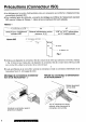
n w J Electrical Connection 2 H # This unit can bs connected to an optional CD Changer (CX-DPO0GOEN], For details consult your nearest Panasonic dealers. 23 Id For connection to a CD changer, refer to the operating instructions of the CD Changer (CX-DPEOBOEN). Caution: # To prevent damage to the unit, be sure to follow the connection diagram below. » Remove the covering of the leads about 5 mm long from their end before connecting.
| Caution: ie To prevent damage to the unit, be sure to follow the connection diagram below. « Remove the covering of the leads about 5 mm long farm their end before connecting. « Do not Insert the power connector into the unit until the wiring is completed. « Be sure to insulate any exposed wires from the car chassis to prevent a possible short circuit. Bundle all cables and keep cable terminals free from touching any metal parts.
ESV Ef F-3.] 42 Speaker Connections Caution: 1. The connections for the speakers should be exclusive as follows. = Grounding should be exclusive. Do not share the grounding with other speakers. * Do not connect the ground lead of the speakers with the chassis. Otherwise, the unit may be damaged. . The speakers for this unit should be able to handle mots than 35W adieu power.
E use 8 J Be sure to use a fuse of the specified rating (10A} when replacing a blown fuse. Fuses with higher capacity rates ins, use of any substitute, or connection without a fuse may result in a fire hazard or damage to the unit. If the a replacement fuse fails, consult your nearest authorized Panasonic Service Center. H 26 Maintenance To clean the exterior of this unit, use soft cloth to wipe the surface. Do not use benzine, thinner, or any other type of solvents.