Cassette Player/Receiver with Changer Control PRG TUNE TA VOL SEL CQ-RD152N CD-C BAND CASSETTE RECEIVER APM PWR TRACK EON EPTY ECT MUTE SCAN DISC LOUD 1 2 3 REPEAT 4 RANDOM 5 MONO/LOC PTY CT DISP AF REG CQ-RD152/RD142/RD132N Operating Instructions Bedienungsanleitung Manuel d’instructions Gebruiksaanwijzing Manuale di istruzioni Manual de Instrucciones Instrukcja ob¬ugi ¡Please read these instructions carefully before using this product and keep this manual for future reference.
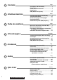
Contents Page Precautions (ISO Connector)....................... 4 Precautions ................................................... 6 Power and Sound Controls.......................... 7 Radio Basics ................................................. 8 RDS (Radio Data System) ............................ 10 Inhaltsverzeichnis Seite Vorsichtsmaßnahmen (ISO-Stecker)........... 4 Vorsichtsmaßnahmen .................................. 26 Stromversorgung und Klangregler ............. 27 Rundfunkempfang .......
Cassette Tape Player Basics ....................... 14 CD Changer Basics ...................................... 16 Installation..................................................... 18 Anti-Theft System ......................................... 21 Electrical Connections ................................. 22 Speaker Connections ................................... 24 Fuse ............................................................... 24 Maintenance ..................................................
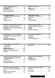
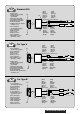
Precautions (ISO Connector) ¡The pin arrangement of the power connector conforms to ISO standard. ¡The pin arrangement of ISO connectors in some cars may differ from the ISO standard. ¡Please check that the pin arrangement of the connector in your car conforms to ISO standard. ¡For car types A and B, change the wiring of the red and yellow leads as shown at right. ¡After connection, insulate the portions marked (C) with insulating tape.
ISO Standard ISO ¡IGN or ACC A7 switched 12V supply ¡Zündschalter (ACC/IGN) ¡Sélecteur ACC/IGN ¡ACC/IGN schakelaar ¡Interruttore ACC/IGN ¡Llave ACC/IGN ¡IGN lub ACC prze¬açczane zasilanie 12 V ¡+12 V Battery (Permanent supply) ¡+12 V-Batterie ¡Batterie +12 V ¡+12 V accu ¡Batteria +12 V ¡+12 V Batería ¡Akumulator ±12 V (Zasilanie sta¬e) A A4 A7 ¡No connection ¡Kein Anschluß ¡Non connecté ¡Niet aangesloten ¡Non collegato ¡Sin conexión ¡Bez po¬aczenia (Yellow) (Gelb) (Jaune) (Geel) (Giallo) (Amarillo) (
E N G L I S H Panasonic welcomes you to their constantly growing family of electronic products owners. We endeavor to give you the advantages of precise electronic and mechanical engineering, manufactured with carefully selected components, and assembled by people who are proud of the reputation their work has built for our company.
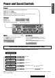
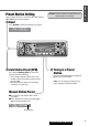
Power and Sound Controls E N G L I S H Power Turn the key in the ignition until the accessory indicator lights. Power on : Press [PWR] . Power off : Press [PWR] again. 2 Note: When the power is switched off and on again, the volume slowly rises to the previous level.(at the volume level is more than level 20) Volume [}VOL] : Up [{VOL] : Down Press and hold for rapid adjustment.
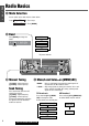
E N G L I S H 3 Radio Basics q Mode Selection You can switch to the radio mode as shown below. Tape Mode From: Eject a tape. CD Changer Mode Press [BAND]. w Band Press [BAND] to change the bands. FM1 FM2 FM3 Band AM (LW/MW) FM stereo indicator PRG TUNE TA VOL SEL CQ-RD152N CD-C BAND BAND CASSETTE RECEIVER APM PWR TRACK EON EPTY ECT [}TUNE] : Higher frequency [{TUNE] : Lower frequency Seek Tuning Press and hold for more than 0.5 seconds then release.
Preset Station Setting Caution: To ensure safety, never attempt to preset stations while you are driving. Up to 5 stations each can be saved in the FM1, FM2, FM3 and AM (LW/MW) preset station memories. E N G L I S H 4 q Band Press [BAND] to select a desired band.
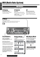
E N G L I S H 5 RDS (Radio Data System) RDS Basics The following functions are available when receiving RDS stations. PS Display CT Service AF (Program Service name) (Clock Time) (Alternative Frequency list) The name of station is displayed instead of the frequency. When receiving an RDS station, the CT (Clock Time) service automatically adjusts the time. “NO CT” is displayed in areas where CT service is not available.
E N G L I S H Traffic Announcements Some RDS FM stations periodically provide traffic information. TP TA (Traffic Program identification) (Traffic Announcements identification) Broadcasting of traffic information Radio announcements on traffic conditions 6 TA Mode Press [TA] to switch the TA mode on. (Press again to switch the TA mode off) TA ON : If the station received is not a TP station, the unit automatically searches for a TP station to tune in to it.
E N G L I S H 7 RDS (Radio Data System) (continued) PTY Reception (Program Type) RDS FM stations provide a program type identification signal. Example: news, rock, classical music, etc. PTY Mode PTY ON Take either following two. ¡Press [PTY] to switch PTY mode on. ¡Press [DISP] to select PTY mode. PTY OFF Take either following two. ¡Press [PTY] again to switch PTY mode off. ¡Press [DISP] to select other than PTY mode. Note: When there is no corresponding program type, “NO PTY” is displayed.
Other RDS Functions EON (Enhanced Other Networks) When EON data is received, the EON indicator lights and the TA and AF functions are expanded as follows. TA : Traffic information from the current and other network stations can be received. AF : The frequency list of preset RDS stations is updated by EON data. EON enables the radio to make fuller use of RDS information. It constantly updates the AF list of preset stations, including that currently tuned in to.
E N G L I S H 9 Cassette Tape Player Basics Mode Selection You can switch to the cassette player mode as shown below. From: CD Changer Mode Insert a cassette tape. Radio Mode Note: You can not select CD Changer mode or Radio mode while tape playing. If you want to select CD Changer mode or Radio mode, eject the tape. Eject Tape Insert and Playback PRG Insert a cassette tape. Playback will start automatically.
E N G L I S H 10 PRG TUNE TA VOL SEL CQ-RD152N CD-C BAND CASSETTE RECEIVER APM PWR TRACK EON EPTY ECT MUTE SCAN DISC LOUD 1 2 3 REPEAT 4 RANDOM 5 MONO/LOC CT PTY DISP AF REG Rewind and Fast Forward The functions of [a] and [f] vary with the tape running direction as shown below.
E N G L I S H 11 CD Changer Basics Mode Selection You can switch to the CD Changer mode as shown below. From: Radio Mode Press [CD-C]. Tape Mode Eject a cassette tape. a Press [CD-C]. Track Number Disc Number PRG TUNE TA VOL SEL CQ-RD152N CD-C CD-C BAND CASSETTE RECEIVER APM PWR TRACK EON EPTY ECT MUTE SCAN DISC LOUD 1 2 REPEAT 3 RANDOM 4 MONO/LOC CT PTY DISP DISP 5 Track Selection Disc Selection [fTRACK] : Advance to the next track.
E N G L I S H Note: The CD Changer functions are designed for an optional CD changer unit. Various Way of Listening 12 PRG TUNE TA VOL SEL CQ-RD152N CD-C BAND CASSETTE RECEIVER APM PWR TRACK EON EPTY ECT MUTE SCAN DISC LOUD 2 1 3 REPEAT 4 RANDOM 5 MONO/LOC CT PTY DISP AF REG Track Scan ¡Press [3] (SCAN). The first 10 seconds of each track of all discs are played in sequence. ¡Press again to cancel. Track Repeat ¡Press [4] (REPEAT). The current track is repeated.
E N G L I S H 13 Installation Preparation ¡Before installation, check the radio operation with antenna and speakers. ¡Disconnect the cable from the negative (–) battery terminal (see caution below). ¡Unit should be installed in a horizontal position with the front end up at a convenient angle, but not more than 30°. ¡We strongly recommend that you wear gloves for installation work to protect yourself from injuries. First complete the electrical connections, and then check them for correctness.
Q’ty E N G L I S H 14 Supplied Hardware ¡When bending the mounting tab of the mounting collar with a screwdriver, be careful not to injure your hands and fingers. 1 Insert Mounting Collar q into the dashboard, and bend the mounting tabs out with a screwdriver. Item No.
E N G L I S H 15 Installation (continued) To Remove the Unit q Remove the removable face plate. Contact Main Unit (a) Press the release button [ ]. PRG ; ; ; ; ; ; ; ; ; ;;;;;;;;;;; ; ; ; ; ; ; ; ; ;;;;;;;;; PRG TA (b) Pull on the right side of the unit. w Remove the trim plate o with a screwdriver. e Pull out the unit while pushing down the lock lever with the dismounting plate u.
Anti-Theft System E N G L I S H This unit is equipped with a removable face plate. Removing this face plate makes the radio totally inoperable. Place Removable Face Plate into Case iRemovable Face Plate Case 16 q Switch off the power of the unit. w Remove the removable face plate. (a Page 20) e Insert the removable face plate with the arrow pointing toward the removable face plate case until you hear a "click". Keep the removable face plate in the case. Then you can bring the plate safely.
E N G L I S H Electrical Connections Cable Wiring Diagram Example : Connection with CD changer CX-DP88N (Option).
Cautions: ¡To prevent damage to the unit, be sure to follow the connection diagram below. ¡Strip about 5 mm of the lead ends for connection (only non-ISO connector cords). ¡Do not insert the power connector into the unit until the wiring is completed. ¡Be sure to insulate any exposed wires to prevent short circuiting with the car chassis. Bundle all cables, and prevent cable terminals from touching any metal parts.
E N G L I S H Speaker Connections Caution: Please follow the instructions given below. Failure to do so will cause damage to the unit and speakers. 19 L + - R+ - (White) + - (White w/black stripe) (Gray) + - (Gray w/black stripe) ¡Use ungrounded speaker only. ¡The maximum speaker output should be 40 W or more. (If used with the optional power amplifier, the speaker output should be higher than the maximum amplifier output.) ¡The speaker impedance should be 4 - 8 Ω.
Specifications General FM Stereo Radio Power Supply Frequency Range Usable Sensitivity Stereo Separation : DC 12 V (11 V - 16 V), Test Voltage 14.4 V, Negative Ground Tone Controls : Bass; ±12 dB at 100 Hz Treble; ±12 dB at 10 kHz Current Consumption : Less than 2.5 A (tape mode, 0.
Matsushita Electric Industrial Co., Ltd. Central P.O.