Order No: PHAAM1111087C1 Indoor Unit CS-E9NKUAW CS-E12NKUAW Outdoor Unit CU-E9NKUA CU-E12NKUA Please file and use this manual together with the service manual for Model No. CU-2E18NBU, Order No. PHAAM1111120A1. WARNING This service information is designed for experienced repair technicians only and is not designed for use by the general public. It does not contain warnings or cautions to advise non-technical individuals of potential dangers in attempting to service a product.
12.3 12.4 12.5 Outdoor Fan Motor Operation ....................31 Airflow Direction..........................................31 Quiet Operation (Cooling Mode/Cooling Area of Dry Mode)...............................................32 12.6 Quiet Operation (Heating) ..........................32 12.7 Powerful Mode Operation...........................33 12.8 Timer Control..............................................33 12.9 Auto Restart Control ...................................33 12.10 Indication Panel ......
1. Safety Precautions Read the following “SAFETY PRECAUTIONS” carefully before perform any servicing. Electrical work must be installed or serviced by a licensed electrician. Be sure to use the correct rating of the power plug and main circuit for the model installed. The caution items stated here must be followed because these important contents are related to safety. The meaning of each indication used is as below.
19. During installation, install the refrigerant piping properly before run the compressor. (Operation of compressor without fixing refrigeration piping and valves at opened condition will cause suck-in of air, abnormal high pressure in refrigeration cycle and result in explosion, injury etc.). 20. During pump down operation, stop the compressor before remove the refrigeration piping.
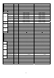
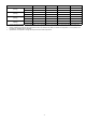
2. Specification Model Indoor CS-E9NKUAW CS-E12NKUAW Outdoor CU-E9NKUA CU-E12NKUA ARI ARI Performance Test Condition Phase, Hz Power Supply Cooling Capacity 230 208 230 Min. Mid. Max. Min. Mid. Max. Min. Mid. Max. Min. Mid. Max. kW 1.20 2.49 3.00 1.20 2.49 3.00 1.20 3.51 3.90 1.20 3.51 3.90 BTU/h 4100 8500 10200 4100 8500 10200 4100 12000 13300 4100 12000 13300 A - 3.5 - - 3.1 - - 5.2 - - 4.
Outdoor Fan Type Propeller Propeller Material PP PP Motor Type DC (8 poles) DC (8 poles) - - Input Power W Output Power Speed Hi Moisture Removal W 40 40 rpm C: 830 H: 780 C: 830 H: 780 L/h (Pt/h) 3 3 3 3 3 3 3 3 3 3 3 3 QLo m /min (ft /min) Lo m /min (ft /min) Me m /min (ft /min) Hi m /min (ft /min) SHi m /min (ft /min) Hi m /min (ft /min) Indoor Airflow Outdoor Airflow 0.6 (1.3) 1.2 (2.5) Cooling : 5.42 (191) Heating : 6.49 (229) Cooling : 6.
1. 2. 3. DRY BULB WET BULB DRY BULB WET BULB Indoor Operation Range (Cooling) Maximum 89.6 73.4 89.6 73.4 Minimum 60.8 51.8 60.8 51.8 Outdoor Operation Range (Cooling) Maximum 109.4 78.8 109.4 78.8 Minimum 5.0 - 5.0 - Indoor Operation Range (Heating) Maximum 86.0 - 86.0 - Minimum 60.8 - 60.8 - Outdoor Operation Range (Heating) Maximum 75.2 64.4 75.2 64.4 Minimum 5.0 3.2 5.0 3.2 Cooling capacities are based on indoor temperature of 27°C DRY BULB (80.
3.
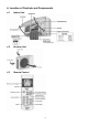
4. Location of Controls and Components 4.1 Indoor Unit 4.2 Outdoor Unit 4.
5. Dimensions 5.
5.
6.
7.
8. Wiring Connection Diagram 8.
8.
9. Electronic Circuit Diagram 9.
9.
10. Printed Circuit Board 10.1 10.1.
10.1.2 Power Printed Circuit Board 10.1.
10.2 10.2.
11. Installation Instruction 11.1 11.1.1 11.1.3 Indoor Unit Do not install the unit in excessive oil fume area such as kitchen, workshop and etc. There should not be any heat source or steam near the unit. There should not be any obstacles blocking the air circulation. A place where air circulation in the room is good. A place where drainage can be easily done. A place where noise prevention is taken into consideration. Do not install the unit near the door way.
11.2 Indoor Unit 11.2.1 How to Fix Installation Plate The mounting wall shall be strong and solid enough to prevent if from the vibration. The center of installation plate should be at more than c at right and left of the wall. The distance from installation plate edge to ceiling should more than d. From installation plate left edge to unit’s left side is e. From installation plate right edge to unit’s right side is f.
11.2.3 Indoor Unit Installation 11.2.3.1 For the right rear piping 11.2.3.2 For the right bottom piping 11.2.3.3 For the embedded piping (This can be used for left rear piping and bottom piping also.
11.2.4 Connect the Cable to the Indoor Unit 1. The inside and outside connection cable can be connected without removing the front grille. 2. Unscrew the conduit cover and fix the conduit connector to conduit cover with lock nut, then secure it against chassis. 3. Connection cable between indoor unit and outdoor unit should be UL listed or CSA approved 4 conductor wires minimum AWG16 in accordance with local electric codes.
11.2.5 Wiring Stripping and connecting requirement 11.2.5.1 1 2 3 Cutting and flaring the piping Please cut using pipe cutter and then remove the burrs. Remove the burrs by using reamer. If burrs are not removed, gas leakage may be caused. Turn the piping end down to avoid the metal powder entering the pipe. Please make flare after inserting the flare nut onto the copper pipes.
11.3 Outdoor Unit 11.3.1 Install the Outdoor Unit After selecting the best location, start installation according to indoor/outdoor unit installation diagram. 1 Fix the unit on concrete or rigid frame firmly and horizontally by bolt nut (ø13/32"). 2 When installing at roof, please consider strong wind and earthquake. Please fasten the installation stand firmly with bolt or nails. Model E9NKUA, E12NKUA 11.3.2 11.3.2.
11.3.2.3 Connecting the piping to outdoor multi Decide piping length and then cut by using pipe cutter. Remove burrs from cut edge. Make flare after inserting the flare nut (locate at valve) onto the copper pipe. Align center of piping to valve and then tighten with torque wrench to the specified torque as stated in the table. 11.3.2.4 Gas Leak Checking Pressure test to system to 400 PSIG with dry nitrogen, in stages. Thoroughly leak check the system.
8. Mount valve caps onto the 2-way valve and the 3-way valve. o Be sure to check for gas leakage. 11.3.3.1 1. 2. 3. 4. 5. 6. 7. 8. Connect the Cable to the Outdoor Unit Remove Top panel. Remove Control Board Cover (Resin and Metal). Remove Plugs. Fix the conduit connectors to the knockout holes with lock-nuts, then secure them against the side panel. All wires pass through conduits.
12. Operation Control 12.1 Basic Function Inverter control, which equipped with a microcomputer in determining the most suitable operation mode as time passes, automatically adjusts output power for maximum comfort always. In order to achieve the suitable operation mode, the microcomputer maintains the set temperature by measuring the temperature of the environment and performing temperature shifting.
12.1.4.2 This mode can be set using remote control and the operation is decided by remote control setting temperature, remote control operation mode, indoor intake air temperature and outdoor air temperature. During operation mode judgment, indoor fan motor (with speed of Lo-) and outdoor fan motor are running for 30 seconds to detect the indoor intake and outdoor air temperature. The operation mode is decided based on below chart. Every 30 minutes, the indoor and outdoor temperature is judged.
[Heating] o According to indoor pipe temperature, automatic heating fan speed is determined as follows. Feedback control o Immediately after the fan motor started, feedback control is performed once every second. o During fan motor on, if fan motor feedback ≥ 2550 rpm or < 50 rpm continue for 10 seconds, then fan motor error counter increase, fan motor is then stop and restart. If the fan motor counter becomes 7 times, then H19 - fan motor error is detected. Operation stops and cannot on back. 12.
12.4.2 Horizontal Airflow The horizontal airflow direction louvers can be adjusted manually by hand. 12.5 Quiet Operation (Cooling Mode/Cooling Area of Dry Mode) Purpose o To provide quiet cooling operation compare to normal operation. Control condition o Quiet operation start condition When “Quiet” button at remote control is pressed. Quiet LED illuminates.
Control contents o Fan speed auto Indoor FM RPM depends on pipe temperature sensor of indoor heat exchanger. Auto fan speed is changed from normal setting to quiet setting of respective fan speed. This is to reduce sound of Hi, Me, Lo for 3dB. o Fan speed manual Manual fan speed for quiet operation is -1 step from setting fan speed. 12.7 When the powerful mode is selected, the internal setting temperature will shift lower up to 35.6°F (for Cooling/Soft Dry) or higher up to 38.
12.10 Indication Panel Note: If POWER LED is blinking, the possible operation of the unit are Hot Start, during Deice operation, operation mode judgment, or ON timer sampling. If Timer LED is blinking, there is an abnormality operation occurs.
13. Operation Control (For Multi Split Connection) During multi split connection, indoor unit’s operation controls are same with single split connection unless specified in this chapter. 13.1 Cooling operation 13.1.1 Thermostat control Capability supply to indoor unit is OFF (Expansion valve closed) when Intake Air Temperature — Internal setting temperature < 28.4°F.
13.4 This mode can be set using remote control and the operation is decided by remote control setting temperature, remote control operation mode, indoor intake and outdoor air temperature. During operation mode judgment, indoor fan motor (with speed of -Lo) and outdoor fan motor are running for 30 seconds to detect the indoor intake and outdoor air temperature. The operation mode is decided based on below chart. Every 180 minutes, the indoor and outdoor temperature is judge.
14. Protection Control 14.1 Protection Control For All Operations 14.1.1 The compressor will not turn on within 3 minutes from the moment operation stops, although the unit is turned on again by pressing OFF/ON button at remote control within this period. This control is not applicable if the power supply is cut off and on again. This phenomenon is to balance the pressure inside the refrigerant cycle. 14.1.
14.1.5 Instructed frequency for compressor operation will be regulated by compressor discharge temperature. The changes of frequency are as below. If compressor discharge temperature exceeds 224.6°F, compressor will be stopped, occurs 4 times per 20 minutes, timer LED will be blinking. (“F97” is indicated.) 14.1.6 Low Frequency Protection Control 1 When the compressor operates at frequency lower than 24Hz continued for 240 minutes, the operation frequency will be changed to 25Hz for 2 minutes.
14.2.2 14.2.3 Freeze Prevention Control 2 Control start conditions o During Cooling operation and soft dry operation During thermo OFF condition, indoor intake temperature is less than 50°F or Compressor stops for freeze prevention control o Either one of the conditions above occurs 5 times in 60 minutes. Control contents o Operation stops o Timer LED blinks and “H99” indicated 14.2.
14.2.6.2 Outdoor Air Temperature Control The maximum current value is regulated when the outdoor air temperature rise above 57.2°F in order to avoid compressor overloading. The compressor will be stopped to avoid compressor overloading. 14.2.6.3 The compressor operating frequency is regulated in accordance to indoor heat exchanger temperature as shown below. If the heat exchanger temperature exceeds 60°C, compressor will stop. 14.2.6.
15. Servicing Mode 15.1 Auto Off/On Button 1 AUTO OPERATION MODE The Auto operation will be activated immediately once the Auto OFF/ON button is pressed. This operation can be used to operate air conditioner with limited function if remote control is misplaced or malfunction. 2 TEST RUN OPERATION (FOR PUMP DOWN/SERVICING PURPOSE) The Test Run operation will be activated if the Auto OFF/ON button is pressed continuously for more than 5 seconds.
Press Auto OFF/ON button to toggle remote control receiving sound. - Short “beep”: Turn OFF remote control receiving sound. - Long “beep”: Turn ON remote control receiving sound. After Auto OFF/ON button is pressed, the 20 seconds counter for Remote Control Receiving Sound OFF/ON Mode is restarted. 15.2 15.2.1 TIMER ▼ To change remote control display from Degree Celsius (°C) to Degree Fahrenheit (°F) o Press continuously for 10 seconds. 15.2.
16. Troubleshooting Guide 16.1 Refrigeration Cycle System In order to diagnose malfunctions, make sure that there are no electrical problems before inspecting the refrigeration cycle. Such problems include insufficient insulation, problem with the power source, malfunction of a compressor and a fan. The normal outlet air temperature and pressure of the refrigeration cycle depends on various conditions, the standard values for them are shown in the table on the right.
16.1.1 Relationship between the condition of the air conditioner and pressure and electric current Carry out the measurements of pressure, electric current, and temperature fifteen minutes after an operation is started.
16.2 16.2.1 Breakdown Self Diagnosis Function Self Diagnosis Function (Three Digits Alphanumeric Code) Once error occurred during operation, the unit will stop its operation, and Timer LED blinks. Although Timer LED goes off when power supply is turned off, if the unit is operated under a breakdown condition, the LED will ON again. In operation after breakdown repair, the Timer LED will not blink. The last error code (abnormality) will be stored in IC memory. 16.2.2 1 2 3 4 5 6 7 8 16.2.
16.
Note: “○” – Frequency measured and fan speed fixed The memory data of error code is erased when the power supply is cut off, or press the Auto Switch until “beep” sound heard following by pressing the CHECK button at remote control. Although operation forced to stop when abnormality detected, emergency operation is possible for certain errors (refer to Error Code Table) by using remote control or Auto OFF/ON button at indoor unit.
16.4 Self-diagnosis Method 16.4.1 H11 (Indoor/Outdoor Abnormal Communication) Malfunction Decision Conditions During startup and operation of cooling and heating, the data received from outdoor unit in indoor unit signal transmission is checked whether it is normal. Malfunction Caused Faulty indoor unit PCB. Faulty outdoor unit PCB. Indoor unit-outdoor unit signal transmission error due to wrong wiring.
16.4.2 H12 (Indoor/Outdoor Capacity Rank Mismatched) Malfunction Decision Conditions During startup, error code appears when different types of indoor and outdoor units are interconnected. Malfunction Caused Wrong models interconnected. Wrong indoor unit or outdoor unit PCBs mounted. Indoor unit or outdoor unit PCBs defective. Indoor-outdoor unit signal transmission error due to wrong wiring.
16.4.3 H14 (Indoor Intake Air Temperature Sensor Abnormality) Malfunction Decision Conditions During startup and operation of cooling and heating, the temperatures detected by the indoor intake air temperature sensor are used to determine sensor errors. Malfunction Caused Faulty connector connection. Faulty sensor. Faulty PCB.
16.4.4 H15 (Compressor Temperature Sensor Abnormality) Malfunction Decision Conditions During startup and operation of cooling and heating, the temperatures detected by the outdoor compressor temperature sensor are used to determine sensor errors. Malfunction Caused Faulty connector connection. Faulty sensor. Faulty PCB.
16.4.5 H16 (Outdoor Current Transformer Open Circuit) Malfunction Decision Conditions A current transformer (CT) is detected by checking the compressor running frequency (≥ rated frequency) and CT detected input current (less than 0.65A) for continuously 20 seconds.
16.4.6 H19 (Indoor Fan Motor – DC Motor Mechanism Locked) Malfunction Decision Conditions The rotation speed detected by the Hall IC during fan motor operation is used to determine abnormal fan motor (feedback of rotation > 2550rpm or < 50rpm) Malfunction Caused Operation stops due to short circuit inside the fan motor winding. Operation stops due to breaking of wire inside the fan motor. Operation stops due to breaking of fan motor lead wires. Operation stops due to Hall IC malfunction.
16.4.7 H23 (Indoor Pipe Temperature Sensor Abnormality) Malfunction Decision Conditions During startup and operation of cooling and heating, the temperatures detected by the indoor heat exchanger temperature sensor are used to determine sensor errors. Malfunction Caused Faulty connector connection. Faulty sensor. Faulty PCB.
16.4.8 H27 (Outdoor Air Temperature Sensor Abnormality) Malfunction Decision Conditions During startup and operation of cooling and heating, the temperatures detected by the outdoor air temperature sensor are used to determine sensor errors. Malfunction Caused Faulty connector connection. Faulty sensor. Faulty PCB.
16.4.9 H28 (Outdoor Pipe Temperature Sensor Abnormality) Malfunction Decision Conditions During startup and operation of cooling and heating, the temperatures detected by the outdoor pipe temperature sensor are used to determine sensor errors. Malfunction Caused Faulty connector connection. Faulty sensor. Faulty PCB.
16.4.10 H30 (Compressor Discharge Temperature Sensor Abnormality) Malfunction Decision Conditions During startup and operation of cooling and heating, the temperatures detected by the outdoor discharge pipe temperature sensor are used to determine sensor errors. Malfunction Caused Faulty connector connection. Faulty sensor. Faulty PCB.
16.4.11 H32 (Outdoor Heat Exchanger Temperature Sensor 2 Abnormality) Malfunction Decision Conditions During startup and operation of cooling and heating, the temperatures detected by the outdoor heat exchanger temperature sensor are used to determine sensor errors. Malfunction Caused Faulty connector connection. Faulty sensor. Faulty PCB.
16.4.12 H33 (Unspecified Voltage between Indoor and Outdoor) Malfunction Decision Conditions The supply power is detected for its requirement by the indoor/outdoor transmission. Malfunction Caused Wrong models interconnected. Wrong indoor unit and outdoor unit PCBs used. Indoor unit or outdoor unit PCB defective.
16.4.13 H36 (Outdoor Gas Pipe Sensor Abnormality) Malfunction Decision Conditions During startup and operation of cooling and heating, the temperatures detected by the outdoor gas pipe temperature sensor are used to determine sensor errors. Malfunction Caused Faulty connector connection. Faulty sensor. Faulty PCB.
16.4.14 H37 (Outdoor Liquid Pipe Temperature Sensor Abnormality) Malfunction Decision Conditions During startup and operation of cooling and heating, the temperatures detected by the outdoor liquid pipe temperature sensor are used to determine sensor errors. Malfunction Caused Faulty connector connection. Faulty sensor. Faulty PCB.
16.4.15 H97 (Outdoor Fan Motor – DC Motor Mechanism Locked) Malfunction Decision Conditions The rotation speed detected by the Hall IC during fan motor operation is used to determine abnormal fan motor. Malfunction Caused Operation stops due to short circuit inside the fan motor winding. Operation stops due to breaking of wire inside the fan motor. Operation stops due to breaking of fan motor lead wires. Operation stops due to Hall IC malfunction. Operation error due to faulty outdoor unit PCB.
16.4.16 H98 (Indoor High Pressure Protection) Error Code will not display (no Timer LED blinking) but store in EEPROM Malfunction Decision Conditions During heating operation, the temperature detected by the indoor pipe temperature sensor is above 140°F.
16.4.17 H99 (Indoor Freeze Prevention Protection: Cooling or Soft Dry) Malfunction Decision Conditions Freeze prevention control takes place (when indoor pipe temperature is lower than 35.
16.4.18 F11 (Indoor Pipe Temperature Sensor Abnormality) Malfunction Decision Conditions When cooling operation, when indoor pipe temperature or indoor heat exchanger temperature sensor is above 113°F. Malfunction Caused Faulty connector connection. Faulty indoor pipe temperature sensor. Faulty indoor main PCB.
16.4.19 F17 (Indoor Standby Units Freezing Abnormality) Malfunction Decision Conditions When the different between indoor intake air temperature and indoor pipe temperature is above 50°F or indoor pipe temperature is below 30.2°F Remark: When the indoor standby unit is freezing, the outdoor unit transfers F17 error code to the corresponding indoor unit and H39 to other indoor unit(s).
16.4.20 F90 (Power Factor Correction Protection) Malfunction Decision Conditions During startup and operation of cooling and heating, when Power Factor Correction (PFC) protection circuitry at the outdoor unit main PCB senses abnormal high DC voltage level. Malfunction Caused DC voltage peak due to power supply surge. DC voltage peak due to compressor windings not uniform. Faulty outdoor PCB.
16.4.21 F91 (Refrigeration Cycle Abnormality) Malfunction Decision Conditions During cooling, compressor frequency = Fcmax. During cooling and heating operation, running current: 0.65A < I < 1.65A. During cooling, indoor intake - indoor pipe < 39.2°F. Malfunction Caused Refrigerant shortage (refrigerant leakage) Poor compression performance of compressor. 2/3 way valve closed. Detection error due to faulty indoor intake air or indoor pipe temperature sensors.
16.4.22 F93 (Compressor Rotation Failure) Malfunction Decision Conditions A compressor rotation failure is detected by checking the compressor running condition through the position detection circuit.
16.4.23 F95 (Cooling High Pressure Abnormality) Malfunction Decision Conditions During operation of cooling, when outdoor unit heat exchanger high temperature data (141.8°F) is detected by the outdoor pipe temperature sensor. Malfunction Caused Outdoor pipe temperature rise due to short circuit of hot discharge air flow. Outdoor pipe temperature rise due to defective of outdoor fan motor. Outdoor pipe temperature rise due to defective outdoor pipe temperature sensor.
16.4.24 F96 (IPM Overheating) Malfunction Decision Conditions During operating of cooling and heating, when IPM temperature data (212°F) is detected by the IPM temperature sensor. Malfunction Caused IPM overheats due to short circuit of hot discharge air flow. IPM overheats due to defective of outdoor fan motor. IPM overheats due to defective of internal circuitry of IPM. IPM overheats due to defective IPM temperature sensor.
16.4.25 F97 (Compressor Overheating) Malfunction Decision Conditions During operation of cooling and heating, when compressor tank temperature data (233.6°F) is detected by the compressor tank temperature sensor. Malfunction Caused Refrigerant shortage (refrigerant leakage). 2/3 way valve closed. Detection error due to faulty compressor tank temperature sensor.
16.4.26 F98 (Input Over Current Detection) Malfunction Decision Conditions During cooling and heating operation, when an input over-current (16.8A) is detected by checking the input current value being detected by current transformer (CT) with the compressor running. Malfunction Caused Over-current due to compressor failure. Over-current due to defective outdoor unit PCB. Over-current due to defective inverter main circuit electrolytic capacitor. Over-current due to excessive refrigerant.
16.4.27 F99 (Output Over Current Detection) Malfunction Decision Conditions During operation of cooling and heating, when an output over-current (18.5A) is detected by checking the current that flows in the inverter DC peak sensing circuitry. Malfunction Caused DC peak due to compressor failure. DC peak due to defective power transistor(s). DC peak due to defective outdoor unit PCB.
17. Disassembly and Assembly Instructions WARNING High Voltage is generated in the electrical parts area by the capacitor. Ensure that the capacitor has discharged sufficiently before proceeding with repair work. Failure to heed this caution may result in electric shocks. 17.1 Indoor Electronic Controllers, Cross Flow Fan and Indoor Fan Motor Removal Procedures 17.1.1 17.1.1.
17.1.1.
17.1.1.3 To remove control board 17.1.1.
18. Technical Data 18.1 18.1.1 CS-E9NK CU-E9NK Cooling Characteristic o Room temperature: 81°F (DBT), 66°F (WBT) o Operation condition: High fan speed o Piping length: 24.6ft o Compressor Frequency : Fc 208 230 Outlet Air Temperature (°F) 61.000 60.000 59.000 58.000 57.000 56.000 55.000 5 10 15 20 25 30 35 40 45 50 55 60 65 70 75 80 85 90 95 100 105 Outdoor Air Temperature (°F) 2.900 Cooling Capacity (kW) 2.700 2.500 2.300 2.100 1.
Piping Length Characteristic Cooling o Room temperature: 81°F (DBT), 66°F (WBT) o Operation condition: High fan speed o Outdoor temperature: 95°F (DBT) o Compressor Frequency : Fc 208 230 Outlet Air Temperature (°F) 59.600 59.400 59.200 59.000 58.800 9 11 13 15 17 19 21 23 25 27 29 31 33 35 37 39 41 43 45 47 49 51 Piping Length (ft) 2.510 Cooling Capacity (kW) 2.490 2.470 2.450 2.430 2.
Heating Characteristic o Room temperature: 68°F (DBT) o Operation condition: High fan speed o Piping length: 24.6ft o Compressor Frequency : Fh 208 230 124.000 Outlet Air Temperature (°F) 119.000 114.000 109.000 104.000 99.000 94.000 89.000 84.000 5 10 15 20 25 30 35 40 45 50 55 60 65 70 75 80 60 65 70 75 80 60 65 70 75 80 60 65 70 75 80 Outdoor Air Temperature (°F) 3.900 Heating Capacity (kW) 3.400 2.900 2.400 1.900 1.
Piping Length Characteristic Heating o Room temperature: 68°F (DBT) o Operation condition: High fan speed o Outdoor temperature: 47°F (DBT), 43°F (WBT) o Compressor Frequency : Fh 208 230 Outlet Air Temperature (°F) 104.900 104.400 103.900 103.400 102.900 102.400 9 11 13 15 17 19 21 23 25 27 29 31 33 35 37 39 41 43 45 47 49 51 Piping Length (ft) 3.300 Heating Capacity (kW) 3.250 3.200 3.150 3.100 3.050 3.000 9 11 13 15 17 19 21 23 25 27 29 31 33 35 37 39 41 43 45 47 49 51 Piping Length (ft) 100.
18.1.2 Cooling Characteristic o Room temperature: 81°F (DBT), 66°F (WBT) o Operation condition: High fan speed o Piping length: 24.6ft o Compressor Frequency : Fc 208 230 Outlet Air Temperature (°F) 59.000 58.000 57.000 56.000 55.000 54.000 5 10 15 20 25 30 35 40 45 50 55 60 65 70 75 80 85 90 95 100 105 Outdoor Air Temperature (°F) 4.200 Cooling Capacity (kW) 4.000 3.800 3.600 3.400 3.200 3.000 2.800 5 10 15 20 25 30 35 40 45 50 55 60 65 70 75 80 85 90 95 100 105 Outdoor Air Temperature (°F) 6.
Piping Length Characteristic Cooling o Room temperature: 81°F (DBT), 66°F (WBT) o Operation condition: High fan speed o Outdoor temperature: 95°F (DBT) o Compressor Frequency : Fc 208 230 Outlet Air Temperature (°F) 58.400 58.200 58.000 57.800 57.600 57.400 9 11 13 15 17 19 21 23 25 27 29 31 33 35 37 39 41 43 45 47 49 51 Piping Length (ft) 3.520 Cooling Capacity (kW) 3.500 3.480 3.460 3.440 3.420 9 11 13 15 17 19 21 23 25 27 29 31 33 35 37 39 41 43 45 47 49 51 Piping Length (ft) 137.
Heating Characteristic o Room temperature: 68°F (DBT) o Operation condition: High fan speed o Piping length: 24.6ft o Compressor Frequency : Fh 208 230 126.000 Outlet Air Temperature (°F) 121.000 116.000 111.000 106.000 101.000 96.000 91.000 86.000 5 10 15 20 25 30 35 40 45 50 55 60 65 70 75 80 60 65 70 75 80 60 65 70 75 80 60 65 70 75 80 Outdoor Air Temperature (°F) 5.200 Heating Capacity (kW) 4.700 4.200 3.700 3.200 2.700 2.200 1.
Piping Length Characteristic Heating o Room temperature: 68°F (DBT) o Operation condition: High fan speed o Outdoor temperature: 47°F (DBT), 43°F (WBT) o Compressor Frequency : Fh 208 230 Outlet Air Temperature (°F) 107.200 106.700 106.200 105.700 105.200 104.700 9 11 13 15 17 19 21 23 25 27 29 31 33 35 37 39 41 43 45 47 49 51 Piping Length (ft) 4.100 Heating Capacity (kW) 4.050 4.000 3.950 3.900 3.850 3.800 9 11 13 15 17 19 21 23 25 27 29 31 33 35 37 39 41 43 45 47 49 51 Piping Length (ft) 98.
19. Exploded View and Replacement Parts List 19.1 Indoor Unit Note The above exploded view is for the purpose of parts disassembly and replacement. The non-numbered parts are not kept as standard service parts.
REF. NO. PART NAME & DESCRIPTION QTY.
19.2 Outdoor Unit Note The above exploded view is for the purpose of parts disassembly and replacement. The non-numbered parts are not kept as standard service parts.
REF. NO. PART NAME & DESCRIPTION QTY.