TECHNICAL & SERVICE MANUAL INDOOR UNIT : CS-MKE9NB4U & CZ-18BT1U CS-MKE12NB4U & CZ-18BT1U CS-KE18NB4UW & CZ-18BT1U DC INVERTER MULTI-SYSTEM AIR CONDITIONER Capacity Indoor Model No. Body (Panel) Product Code No.
SAFETY PRECAUTIONS • Before doing repair work, please read the " SAFETY PRECAUTIONS" carefully and fully understand them. • The precautionary items here are divided into " Warning" and " Caution" items. Items in particular which may cause death or serious injury to the service personnel if the work is not performed correctly, are included in the " Warning" table. However, even precautionary items identified as " Caution" also have the potential for serious consequences if not performed correctly.
Warning If refrigerant gas blows off during the work, do not touch the refrigerant gas as it may cause frostbite. Prohibit If refrigerant gas leaks during the work, ventilate the room. If refrigerant gas catches fire, harmful gas may be generated. Do not mix any gas other than the specified refrigerant gas in the refrigerating cycle. If air or other contaminants mix with the gas, pressure will become extremely high in the refrigerating cycle, which may cause a unit breakdown.
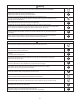
TABLE OF CONTENTS Page SAFETY PRECAUTIONS ............................................................................................................. 2 TABLE OF CONTENTS .................................................................................................................... 4 APPLICABLE MULTI-OUTDOOR UNITS .................................................................................... 6 1. OPERATING RANGE ..............................................................................
Page APPENDIX D Operating Instructions ...........................................................................................A-4 (CZ-RD515U) APPENDIX E INSTALLATION INSTRUCTIONS ............................................................................
APPLICABLE MULTI-OUTDOOR UNITS Multi-Outdoor Unit 3-Room 4-Room 4-Room CU-3KE19NBU CU-4KE24NBU CU-4KE31NBU CS-MKE9NB4U & CZ-18BT1U YES YES YES CS-MKE12NB4U & CZ-18BT1U YES YES YES CS-KE18NB4UW & CZ-18BT1U YES YES YES Indoor Unit 6
1. OPERATING RANGE Temperature Cooling Heating Indoor Air Intake Temp. Outdoor Air Intake Temp.
2. SPECIFICATIONS 2-1. Unit Specifications 2-1-1. Indoor Unit CS-MKE9NB4U & CZ-18BT1U <230V> Type Semi-Concealed Type Indoor Unit Electrical Rating Performance Voltage Rating 230V Single-Phase 60Hz Heating Cooling BTU/h 12,300 9,000 kW 3.6 2.65 ft3/min (m3/h) 221 (376) / 206 (350) / 194 (330) 247 (420) / 235 (399) / 224 (381) Pints/h 3.4 V 187 to 253 A 0.12 0.
Indoor Unit CS-MKE9NB4U & CZ-18BT1U <208V> Type Semi-Concealed Type Indoor Unit Electrical Rating Performance Voltage Rating 208V Single-Phase 60Hz Cooling Heating BTU/h 12,300 9,000 kW 3.6 2.65 ft3/min (m3/h) 221 (376) / 206 (350) / 194 (330) 247 (420) / 235 (399) / 224 (381) Pints/h 3.4 V 187 to 253 A 0.11 0.
2-1-2. Indoor Unit CS-MKE12NB4U & CZ-18BT1U <230V> Type Semi-Concealed Type Indoor Unit Electrical Rating Performance Voltage Rating 230V Single-Phase 60Hz Cooling Heating BTU/h 13,600 11,900 kW 4.0 3.5 ft3/min (m3/h) 235 (399) / 206 (350) / 194 (330) 268 (455) / 247 (420) / 224 (381) Pints/h 4.26 V 187 to 253 A 0.11 0.
Indoor Unit CS-MKE12NB4U & CZ-18BT1U <208V> Type Semi-Concealed Type Indoor Unit Electrical Rating Performance Voltage Rating 208V Single-Phase 60Hz Cooling Heating BTU/h 13,600 11,900 kW 4.0 3.5 ft3/min (m3/h) 235 (399) / 206 (350) / 194 (330) 268 (455) / 247 (420) / 224 (381) Pints/h 4.26 V 187 to 253 A 0.12 0.
2-1-3. Indoor Unit CS-KE18NB4UW & CZ-18BT1U <230V> Type Semi-Concealed Type Indoor Unit Electrical Rating Performance Voltage Rating 230V Single-Phase 60Hz Heating Cooling BTU/h 20,400 17,500 kW 6.0 5.15 ft3/min (m3/h) 341 (579) / 294 (500) / 253 (430) 383 (651) / 324 (551) / 265 (450) Pints/h 4.89 V 187 to 253 A 0.19 0.
Indoor Unit CS-KE18NB4UW & CZ-18BT1U <208V> Type Semi-Concealed Type Indoor Unit Electrical Rating Performance Voltage Rating 208V Single-Phase 60Hz Heating Cooling BTU/h 20,400 17,500 kW 6.0 5.15 ft3/min (m3/h) 341 (579) / 294 (500) / 253 (430) 383 (651) / 324 (551) / 265 (450) Pints/h 4.89 V 187 to 253 A 0.2 0.
2-2. Major Component Specifications 2-2-1. Indoor Unit Indoor Unit (Body) CS-MKE9NB4U Control PCB CB-CS-MKE9NB4U Microprocessor 250V 3A Part No. Controls Control Circuit Fuse Fan Type Q'ty ... Dia. and Length Turbo 1 ... D12-5/8 / L5-3/4 (D322/L147) inch (mm) Fan Motor Type Model ... Q'ty No. of Poles Rough Measure RPM (Cool / Heat) Rating Voltage / Nominal Output Coil Resistance Ohm (Ambient Temp.
Indoor Unit (Body) CS-MKE12NB4U Control PCB Part No. Controls Control Circuit Fuse CB-CS-MKE12NB4U Microprocessor 250V 3A Fan Type Q'ty ... Dia. and Length Turbo 1 ... D12-5/8 / L5-3/4 (D322/L147) inch (mm) Fan Motor Type Model ... Q'ty No. of Poles Rough Measure RPM (Cool / Heat) Rating Voltage / Nominal Output Coil Resistance Ohm (Ambient Temp. 68 °F (20 °C)) Safety Device Type Over- Current Protection Over- Heat Protection Run Capacitor Micro F VAC DC Motor SIC-62FW-D866-2 ...
Indoor Unit (Body) CS-KE18NB4UW Control PCB Part No. Controls Control Circuit Fuse CB-CS-KE18NB4U Microprocessor 250V 3A Fan Type Q'ty ... Dia. and Length Turbo 1 ... D12-5/8 / L5-3/4 (D322/L147) inch (mm) Fan Motor Type Model ... Q'ty No. of Poles Rough Measure RPM (Cool / Heat) Rating Voltage / Nominal Output Coil Resistance Ohm (Ambient Temp. 68 °F (20 °C)) Safety Device Type Over- Current Protection Over- Heat Protection Run Capacitor Micro F VAC DC Motor SIC-62FW-D866-2 ...
2-3.
7-23/32 1-27/32 1 2 3 4 5 6 7 8 1-3/32 2-3/32 Less than 31/32 22-5/8 (575) 5-9/16 25/32 7 2 2 1 2 Less than 31/32 Fresh air intake duct connection port (dia. 3-7/8") Suspension bolt hole (4 - 1/2" x 1-1/8" hole) Power supply port Drain tube connection port VP20 (outer dia. 1") Refrigerant tubing (gas tube) dia. 1/2" (flared) Refrigerant tubing (liquid tube) dia.
4. REFRIGERANT FLOW DIAGRAM 4-1. Refrigerant Flow Diagram Indoor Unit CS-MKE9NB4U & CZ-18BT1U CS-MKE12NB4U & CZ-18BT1U Indoor unit Strainer Heat exchanger O.D. 3/8" (9.52 mm) O.D. 1/4" (6.35 mm) Cooling cycle Heating cycle CS-KE18NB4UW & CZ-18BT1U Indoor unit Heat exchanger O.D. 1/2" (12.7 mm) Strainer Indoor Unit O.D. 1/4" (6.
2 3 20 WHT RED BLK AC1 AC2 SI FM FERRITE CORE DP DRAIN PUMP 1 3 1 3 DP 3P (BLU) 3P (RED) GRN/YEL CONTROLLER 1 2 3 4 5 6 1 2 3 4 5 6 DCM 6P (BLU) 6P (WHT) RED FAN MOTOR BLK WHT YEL BLU BOX 1 2 3 4 5 6 7 1 2 3 4 5 6 7 PWM/POW 7P (RED) SERIAL 1 1 2P (WHT) 2 2 GRN RED WHT BRN RED ORG YEL PNK BLU VLT BOX 1 2 3 4 5 6 7 1 2 3 4 5 6 7 PWM/POW 7P (RED) 1 1 SERIAL 2 2 2P (WHT) IND LAMP ASSY 1 2 3 4 5 6 7 8 9 10 1 2 3 4 5 6 7 8 9 10 1 2 3 4 1 2 3 4 RC 4P (WHT) FLAP (R) 1 2 3 4 5 6 1 2 3 4 5
6. MAINTENANCE 6-1. Disassembly Procedure To avoid electrical shock hazard, be sure to disconnect power before attempting to disassemble the unit. When a footstool, etc. is used for disassembling the indoor unit, be careful not to fall down. If you fall down, you might be injured seriously. Warning 6-1-1. Remove the air intake grill. (1) Slide the 2 latches each to the corresponding arrow direction. (Fig. 1 and Fig. 2) Open downward the air intake grill located on the latch side.
6-1-3. Remove the ceiling panel. (1) Open the clamp (4 locations) and remove the 2 lead wires from the clamps. (Fig. 6) (2) Remove the 4 screws fixing the corner cover (at 3 locations) and indicator cover (at 1 location). (Fig. 6) (3) Press the center 1 of the cover and remove the cover with the section 2 pulled down. (Fig. 7) (4) Remove the strap (3 locations) from the hook on the ceiling panel. (Fig. 8) NOTE There is no strap on the indicator cover.
6-1-4. Remove the indoor air temperature sensor. (1) Disconnect the connector CN08 (ROOM 2P) in the control box and remove the indoor air temperature sensor. (Fig. 10) Indoor air temperature sensor CN08 Fig.10 6-1-5. Remove the power box and control box. (1) Remove a screw and remove the terminal cover. (Fig. 11) (2) Remove the 2 screws and remove the power box cover. (Fig. 11) (3) Disconnect the power lines (No. 1 and No. 2) / signal line (No. 3) and ground cable from the terminals in the power box.
(4) Disconnect the connector CN07 (DP 2P) in the power box. (Fig. 13) Remove a screw and disconnect the ground cable. (Fig. 13) (5) Disconnect the connector CN03 (DCM 6P) in the power box. (Fig. 14) (6) Remove the 4 screws and remove the power box. (Fig. 14) (7) Disconnect the connectors CN06 (FS 3P) and CN09 (COIL-1 2P) in the control box. (Fig. 15) (8) Remove the 2 screws and remove the control box. (Fig. 15) Screw Ground cable 1 2 3 CN07 Fig.13 Screw Screw Screw Screw CN03 Fig.
NOTE For the removal of the following components, perform any work after removing the indoor unit (main body) from the ceiling. Main body lower section Heat exchanger sensor Drain pump Float switch Turbo fan Fan motor Heat exchanger 1. Perform the work after draining the water to prevent the water leakage from the drain pan. • Put a bucket, etc., under the drain cap and remove the drain cap to drain the water. (Fig. 16) 2.
6-1-7. Remove the heat exchanger sensor. (1) Remove the heat exchanger sensor from the sensor holder. (Fig. 19) Heat exchanger sensor Holder Fig.19 6-1-8. Remove the drain pump and float switch. (1) Remove the 2 screws (Fig. 20) (2) Loosen the clamp and disconnect the drain hose from the drain pump. (Fig. 20) (3) Remove the drain pump from the main body upper section. (Fig. 20) (4) Remove a nut and remove the float switch. (Fig. 21) Screw Drain pump Float switch Nut Drain hose Clamp Fig.20 Fig.
6-1-9. Remove the turbo fan and fan motor. (1) Remove a nut and remove the turbo fan. (Fig. 22) (2) Remove the 2 screws and 3 nuts, and remove the fan motor. (Fig. 23) Turbo fan Screw Nut Nut Fan motor Fig.22 Fig.23 6-1-10. Remove the heat exchanger. (1) Remove the 3 screws. (Fig. 24) (2) Remove the 3 screws. (Fig. 25) (3) Remove the heat exchanger from the main body upper section with the heat exchanger lifted. Heat exchanger Screw Screw Main body upper section Screw Fig.24 Fig.
7. FUNCTIONS 7-1. Operation Functions Emergency operation SENSOR DRY Emergency operation is available when the remote controller malfunctions, has been lost, or otherwise cannot be used. During DRY operation, the system adjusts the room temperature and fan speed according to the conditions in the room, in order to maintain a comfortable room environment. SENSOR DRY operation • DRY operation is as shown in the figure below.
HIGH POWER NIGHT SETBACK This function acts to raise the power but keeps the AC system in the same operating mode. This function is set with the HIGH POWER button on the remote controller. (It can be set regardless of the temperature and fan speed settings.) When NIGHT SETBACK operation is set, the temperature and fan speed settings will be adjusted automatically to allow comfortable sleep. When NIGHT SETBACK operation is set, " mark" appears on the remote controller.
7-2. Protective Functions Overload prevention during heating Cold-air prevention during heating Indoor heat exchanger temperature °F(°C) During HEAT operation, the temperature of the indoor heat exchanger is used to control the frequency and lessen the load on the compressor before the protective device is activated. Approx. 127 (53) During heating, the fan speed is set to "LL" (very low) or stopped. As the temperature of the indoor heat exchanger rises, the fan speed is changed to the set speed.
8. TROUBLESHOOTING (BEFORE CALLING FOR SERVICE) 8-1. Precautions before Performing Inspection or Repair After checking the self-diagnostics monitor, turn the power OFF before starting inspection or repair. High-capacity electrolytic capacitors are used inside the outdoor unit controller (inverter). They retain an electrical charge (charging voltage DC 310V) even after the power is turned OFF, and some time is required for the charge to dissipate.
(1) Self-diagnostics Lamps INDOOR UNIT OPERATION button OPERATION lamp TIMER lamp HIGH POWER lamp REMOTE CONTROL receiver Since the indications cover various units, the corresponding parts listed below may not be present in some models. .... OFF INDICATION ON INDOOR UNIT OPERATION TIMER HIGH POWER CODE S01 S02 DIAGNOSIS CONTENTS .... ON POSSIBLE MALFUNCTION (1) OPEN OR SHORT CIRCUIT IN SENSOR ROOM TEMP. SENSOR TROUBLE (2) POOR CONTACT AT CONNECTOR OR OPEN CIRCUIT AT TERMINAL PRESS-FIT LOCATION.
(2) If the self-diagnostics function fails to operate Check the indoor unit. • No indicators illuminate and the indoor fan does not rotate. • Check the power voltage. Blown Is the fuse blown? Normal Replace the circuit board or the fuse. Replace the controller. 8-3. Checking the Indoor and Outdoor Units (1) Checking the indoor unit No. 1 Control Use the remote controller to operate the unit in "TEST run" mode.
(3) Serial Communication Error Identification Procedure If the lamps on the main body show the following conditions after the completion of self-diagnostics, a communication error between the indoor unit and outdoor unit might be considered. In such a case, identify the breakdown section by using the following procedure. Refer to "Method of Self-Diagnostics" for the self-diagnostics procedure.
( Continued from the previous page A. ) A ( Continued from the previous page B. ) B Is the voltage of about DC22V to 24V given between the terminals 2 and 3 on the indoor unit terminal strip (Serial Communication Line) ? (Fig. 2) Yes No Defect in the indoor unit P.C. board Defect or connection error in the inter-unit cable Outdoor Unit 1. Turn OFF the power and wait until the power lamp (LED) of the outdoor unit controller is turned OFF. 2.
(3-2) Condition: E12 Troubleshooting Serial Communication Outdoor Unit 1 2 3 4 5 6 Power 1. Turn off the power and wait until the power lamp (LED) of the outdoor unit controller is turned OFF. 2. Disconnect the cable from the terminal 3 on the Outdoor unit terminal strip. (Fig. 6) 1 2 3 Indoor Unit Fig. 6 1. Turn ON the power and operate the system using the remote controller or the operation button on the indoor unit. 2. Perform the self-diagnosis five seconds after the operation start.
8-4. Trouble Diagnosis of Fan Motor 8-4-1. Indoor Fan Motor This indoor DC fan motor contains an internal control PCB. Therefore, it is not possible to measure the coil resistance, and the following procedure should be used to check the motor. To perform diagnosis, operate the unit in cooling mode with indoor fan speed "High". Next, make sure that the indoor unit receive the signals from the remote controller when the ON/OFF operation button is pressed.
8-5. Noise Malfunction and Electromagnetic Interference An inverter A/C operates using pulse signal control and high frequencies. Therefore, it is susceptible to the effects of external noise, and is likely to cause electromagnetic interference with nearby wireless devices. A noise filter is installed for ordinary use, preventing these problems. However, depending on the installation conditions, these effects may still occur. Please pay attention to the points listed below.
APPENDIX A Operating Instructions CS-MKE9NB4U & CZ-18BT1U CS-MKE12NB4U & CZ-18BT1U (852-6-4181-219-00-2) A-1
Operating Instructions Split System Air Conditioner Model No. Indoor Units Outdoor Units CS-MKE9NB4U CS-MKE12NB4U CU-3KE19NBU CU-4KE24NBU CU-4KE31NBU Ceiling Panel CZ-18BT1U This air conditioner uses the refrigerant R410A. Before operating the unit, read these operating instructions thoroughly and keep them for future reference.
FEATURES This air conditioner is an inverter type unit that automatically adjusts capability as appropriate. Details on these functions are provided below; refer to these descriptions when using the air conditioner. • Microprocessor Controlled Operation • Air Sweep Control The interior compartment of the remote controller contains several features to facilitate automatic operation, easy logically displayed for easy use.
INSTALLATION LOCATION • We recommend that this air conditioner be installed properly by qualified installation technicians in accordance with the Installation Instructions provided with the unit. • Before installation, check that the voltage of the electric supply in your home or office is the same as the voltage shown on the nameplate. • Do not install this air conditioner where there are fumes or flammable gases, or in an extremely humid space such as a greenhouse.
NAMES OF PARTS UNIT DISPLAY AND OPERATION BUTTON INDOOR UNIT INDOOR UNIT Air Intakes OPERATION button OPERATION lamp Air Outlet! (4 locations) TIMER lamp HIGH POWER lamp REMOTE CONTROL receiver Remote Controller IMPORTANT Refrigerant Tubes OUTDOOR UNIT Drain Hose Avoid using radio equipment such as mobile phone near (within 4 ft. (1.2 m)) the remote control receiver. Some radio equipment may cause malfunction of the unit.
REMOTE CONTROLLER (DISPLAY) Displayed when transmitting data Displayed when indoor unit sensor is in use Displayed when setting temperature Displayed when temperature is shown Displayed when setting timer Displayed when the time display is set to 12-hour time. Symbols (1) Operation mode (4) Timer AUTO ..................................... 24-hour clock with ON/OFF program Timer ....................... HEAT ...................................... ON Timer. .............................. MILD DRY .....
REMOTE CONTROLLER Transmitter When you press the buttons on the remote controller, the mark appears in the display to transmit the setting changes to the receiver in the air conditioner. Display Information on the operating conditions is displayed while the remote controller is switched on. If the unit is turned off, FLAP setting and FAN SPEED setting are not displayed.
Sensor A temperature sensor inside the remote controller senses the room temperature. ON/OFF operation button This button is for turning the air conditioner on and off. 1 HR. TIMER button (1-HOUR OFF TIMER) : When you press this button, regardless of whether the unit is operating or stopping, the unit operates for one hour and then shuts down. Temperature setting buttons (TEMP.) Press the button to increase the set temperature. Press the button to reduce the set temperature.
USING THE REMOTE CONTROLLER HOW TO INSTALL BATTERIES HOW TO USE THE REMOTE CONTROLLER When using the remote controller, always point the unit’s transmitter head directly at the air conditioner’s receiver. Air Conditioner (Indoor unit) Receiver ACL button 1. Slide the cover in the direction indicated by the arrow and remove it. 2. Install two AAA alkaline batteries. Make sure the batteries point in the direction marked in the battery compartment. 3.
OPERATION WITH THE REMOTE CONTROLLER 1. Automatic Operation 2. Manual Operation The air conditioner calculates the difference between the thermostat setting and room temperature, and automatically determines the mode to operate under cooling or heating. Then, the air conditioner continuously operates under the mode selected at initial operation.
3. Adjusting the Fan Speed B. In Heating Mode: ( A. Automatic fan speed Simply set the FAN SPEED selector button to the position. This automatically sets the best fan speed for the room temperature. B. Manual fan speed If you want to adjust fan speed manually during operation, just set the FAN SPEED selector button as desired. [ , , or ] 4.
SPECIAL REMARKS ‘‘DRY’’ ( SETTING THE TIMER ) Operation How it works? • Once the room temperature reaches the level that was set, the unit’s operation frequency is changed automatically. • During DRY operation, the fan speed automatically runs at lower speed for providing a comfortable breeze. • ‘‘DRY’’ operation is not possible if the indoor temperature is 59 °F or less.
2. How to set the OFF time 4. How to set daily ON/OFF repeat timer (Example) To stop the air conditioner at 11:00 am. (Example) To start operation at 7:10 am. and stop the air conditioner at 11:00 am. Operation 1. Press the OFF TIME setting button once. Indication 10:30 pm. Present time 11:00 am. OFF The timer indication is displayed, and the present OFF time is shown. 2. Press the Advance, Return The timer indication ( , ) button until AM 11:00 blinks. is displayed.
USING THE 1-HOUR OFF TIMER 1. 1-Hour OFF Timer This function causes the unit to operate for one hour and then stop, regardless of whether the unit is on or off when this button is pressed. The indicator in the display indicates that this function is operating. Setting procedure: Regardless of whether the unit is operating or stopped, press the 1 HR. TIMER button. appears in the display.
OPERATION WITHOUT THE REMOTE CONTROLLER CARE AND CLEANING • Cleaning and maintenance operations must be carried out by specially trained personnel. While working in high places, slipping or falling may result in serious injury. • For safety, be sure to turn the air conditioner off and also to disconnect the power before cleaning. • Do not pour water on the indoor unit to clean it. This will damage the internal components and cause an electric shock hazard.
Air filter The air filter collects dust and other particles from the air and should be cleaned once every 6 months. If the filter gets blocked, the efficiency of the air conditioner drops greatly. How to remove the air intake grille 1. Open the air intake grille. 2. Detach the safety cord from the frame (remember to attach it again after cleaning or maintenance). 3. Hold on the air intake grille and pull it towards you to detach the NOTE two air intake grille hinges.
TROUBLESHOOTING (BEFORE CALLING FOR SERVICE) If your air conditioner does not work properly, first check the following points before requesting service. If it still does not work properly, contact your dealer or service center. Trouble Air conditioner does not run at all. Possible Cause Remedy 1. Power failure. 1. Restore power. 2. Leakage circuit breaker tripped. 2. Contact service center.
SPECIFICATIONS Model No. Power Source Cooling Capacity Heating Capacity Operation Cooling Operation (H/M/L) Sound Heating Operation (H/M/L) Unit Dimensions (H×W×D) Net Weight Model No. Power Source Cooling Capacity Heating Capacity Operation Cooling Operation (Hi) Sound Heating Operation (Hi) Unit Dimensions (H×W×D) Net Weight kW BTU/h kW BTU/h dB(A) dB(A) inch(mm) lbs.(kg) Net Weight 35.3(16.0) 35.3(16.0) Outdoor Unit CU-4KE31NBU CU-4KE24NBU Single-phase, 208-230 V, 60 Hz 9.00 [ 2.90 ~ 9.00 ] 5.
APPENDIX B Operating Instructions CS-KE18NB4UW & CZ-18BT1U (852-6-4181-213-00-2) A-2
Operating Instructions Split System Air Conditioner Model No. Indoor Units Outdoor Units (For Single use) CS-KE12NB41 CS-KE18NB4UW CU-KE12NK1 CU-KE18NKU (For Multiple use) CU-3KE19NBU CU-4KE24NBU CU-4KE31NBU Ceiling Panel CZ-18BT1U This air conditioner uses the refrigerant R410A. “Multiple use” is applied for the model CS-KE18NB4UW only.
FEATURES This air conditioner is an inverter type unit that automatically adjusts capability as appropriate. Details on these functions are provided below; refer to these descriptions when using the air conditioner.
INSTALLATION LOCATION • We recommend that this air conditioner be installed properly by qualified installation technicians in accordance with the Installation Instructions provided with the unit. • Before installation, check that the voltage of the electric supply in your home or office is the same as the voltage shown on the nameplate. • Do not install this air conditioner where there are fumes or flammable gases, or in an extremely humid space such as a greenhouse.
NAMES OF PARTS UNIT DISPLAY AND OPERATION BUTTON INDOOR UNIT INDOOR UNIT Air Intakes OPERATION button OPERATION lamp Air Outlet! (4 locations) TIMER lamp HIGH POWER lamp REMOTE CONTROL receiver Remote Controller IMPORTANT Refrigerant Tubes OUTDOOR UNIT Drain Hose Avoid using radio equipment such as mobile phone near (within 4 ft. (1.2 m)) the remote control receiver. Some radio equipment may cause malfunction of the unit.
REMOTE CONTROLLER (DISPLAY) Displayed when transmitting data Displayed when indoor unit sensor is in use Displayed when setting temperature Displayed when temperature is shown Displayed when setting timer Displayed when the time display is set to 12-hour time. Symbols (1) Operation mode (4) Timer AUTO ..................................... 24-hour clock with ON/OFF program Timer ....................... HEAT ...................................... ON Timer. .............................. MILD DRY .....
REMOTE CONTROLLER Transmitter When you press the buttons on the remote controller, the mark appears in the display to transmit the setting changes to the receiver in the air conditioner. Display Information on the operating conditions is displayed while the remote controller is switched on. If the unit is turned off, FLAP setting and FAN SPEED setting are not displayed.
Sensor A temperature sensor inside the remote controller senses the room temperature. ON/OFF operation button This button is for turning the air conditioner on and off. 1 HR. TIMER button (1-HOUR OFF TIMER) : When you press this button, regardless of whether the unit is operating or stopping, the unit operates for one hour and then shuts down. Temperature setting buttons (TEMP.) Press the button to increase the set temperature. Press the button to reduce the set temperature.
USING THE REMOTE CONTROLLER HOW TO INSTALL BATTERIES HOW TO USE THE REMOTE CONTROLLER When using the remote controller, always point the unit’s transmitter head directly at the air conditioner’s receiver. Air Conditioner (Indoor unit) Receiver ACL button 1. Slide the cover in the direction indicated by the arrow and remove it. 2. Install two AAA alkaline batteries. Make sure the batteries point in the direction marked in the battery compartment. 3.
OPERATION WITH THE REMOTE CONTROLLER 1. Automatic Operation 2. Manual Operation When the remote controller’s S/M switch is at the “S” (Single) position This unit automatically switches between cooling operation and heating operation according to the difference between the room temperature and the temperature setting.
3. Adjusting the Fan Speed A. In Cooling and DRY Mode: ( A. Automatic fan speed Simply set the FAN SPEED selector button to the position. This automatically sets the best fan speed for the room temperature. B.
• When the HIGH POWER button is pressed, the unit operates at maximum output for 30 minutes, regardless of the desired temperature. The fan speed is 1 step above “High”. • HIGH POWER Mode cannot be used when the operation mode is in Automatic Operation. SETTING THE TIMER NOTE • When set to High fan speed during heating operation, the fan runs at High fan speed even though the mark is displayed. • Depending on the operating conditions, the fan speed may be increased by a small amount only.
2. How to set the OFF time 4. How to set daily ON/OFF repeat timer (Example) To stop the air conditioner at 11:00 am. (Example) To start operation at 7:10 am. and stop the air conditioner at 11:00 am. Operation 1. Press the OFF TIME setting button once. Indication 10:30 pm. Present time 11:00 am. OFF The timer indication is displayed, and the present OFF time is shown. 2. Press the Advance, Return The timer indication ( , ) button until AM 11:00 blinks. is displayed.
USING THE 1-HOUR OFF TIMER 1. 1-Hour OFF Timer This function causes the unit to operate for one hour and then stop, regardless of whether the unit is on or off when this button is pressed. The indicator in the display indicates that this function is operating. Setting procedure: Regardless of whether the unit is operating or stopped, press the 1 HR. TIMER button. appears in the display.
OPERATION WITHOUT THE REMOTE CONTROLLER CARE AND CLEANING • Cleaning and maintenance operations must be carried out by specially trained personnel. While working in high places, slipping or falling may result in serious injury. • For safety, be sure to turn the air conditioner off and also to disconnect the power before cleaning. • Do not pour water on the indoor unit to clean it. This will damage the internal components and cause an electric shock hazard.
Air filter The air filter collects dust and other particles from the air and should be cleaned once every 6 months. If the filter gets blocked, the efficiency of the air conditioner drops greatly. How to remove the air intake grille 1. Open the air intake grille. 2. Detach the safety cord from the frame (remember to attach it again after cleaning or maintenance). 3. Hold on the air intake grille and pull it towards you to detach the NOTE two air intake grille hinges.
TROUBLESHOOTING (BEFORE CALLING FOR SERVICE) If your air conditioner does not work properly, first check the following points before requesting service. If it still does not work properly, contact your dealer or service center. Trouble Air conditioner does not run at all. Possible Cause Remedy 1. Power failure. 1. Restore power. 2. Leakage circuit breaker tripped. 2. Contact service center. 3. Line voltage is too low. 3. Consult your electrician or dealer. 4.
SPECIFICATIONS • For Single use Model No. Power Source Cooling Capacity Heating Capacity Cooling Outdoor (Hi) Operation Operation Indoor(H/M/L) Sound Heating Outdoor (Hi) Operation Indoor(H/M/L) Unit Dimensions (H×W×D) Net Weight kW BTU/h kW BTU/h dB(A) dB(A) inch(mm) lbs.(kg) Outdoor Unit Indoor Unit CU-KE12NK1 CS-KE12NB41 Single-phase, 115 V, 60 Hz 3.50 [ 0.90 ~ 3.50 ] 11,900 [ 3,000 ~ 11,900 ] 4.00 [ 0.90 ~ 4.
SPECIFICATIONS (CONTINUED) • For Multiple use kW BTU/h kW BTU/h Indoor Unit CS-KE18NB4UW Single-phase, 208-230 V, 60 Hz 5.15 17,500 6.00 20,400 dB(A) 44/40/36 dB(A) 44/40/36 Model No. Power Source Cooling Capacity Heating Capacity Operation Sound Cooling Operation (H/M/L) Heating Operation (H/M/L) Unit Dimensions (H×W×D) Net Weight 11-5/32×22-5/8×22-5/8 (283×575×575) 35.3(16.0) inch(mm) lbs.(kg) • For Multiple use Model No.
APPENDIX C INSTALLATION INSTRUCTIONS CS-MKE9NB4U & CZ-18BT1U CS-MKE12NB4U & CZ-18BT1U CS-KE18NB4UW & CZ-18BT1U (852-6-4190-585-00-1) A-3
For Indoor Unit INSTALLATION INSTRUCTIONS Split System Air Conditioner Contents This air conditioner uses the refrigerant R410A. NOTE Page External diameter of service port R410A: 5/16" Model Combinations Combine indoor and outdoor units only as listed below. IMPORTANT! Please Read Before Starting .................................. 2 1. GENERAL .......................................................... 4 1-1. Tools Required for Installation (not supplied) 1-2. Accessories Supplied with Unit 1-3.
IMPORTANT! Please Read Before Starting When Transporting Be careful when picking up and moving the indoor and outdoor units. Get a partner to help, and bend your knees when lifting to reduce strain on your back. Sharp edges or thin aluminum fins on the air conditioner can cut your fingers. This air conditioning system meets strict safety and operating standards. As the installer or service person, it is an important part of your job to install or service the system so it operates safely and efficiently.
$SSO\ UHIULJHUDQW OXEULFDQW WR WKH PDWFKLQJ VXUIDFHV RI the flare and union tubes before connecting them, then tighten the nut with a torque wrench for a leak-free connection. &OHDQ XS WKH VLWH DIWHU \RX ILQLVK UHPHPEHULQJ WR FKHFN that no metal scraps or bits of wiring have been left inside the unit being serviced.
1. General This booklet briefly outlines where and how to install the air conditioning system. Please read over the entire set of instructions for the indoor and outdoor units and make sure all accessory parts listed are with the system before beginning. 1-1. Tools Required for Installation (not supplied) 1. Standard screwdriver 6. Sabre saw or key hole saw 2. Phillips head screwdriver 7. Hacksaw 3. Knife or wire stripper 8. Core bits 4. Tape measure 9. Hammer 5. Carpenter’s level 10. Drill 11. 12. 13. 14.
1-5. Additional Materials Required for Installation 1. 2. Refrigeration (armored) tape Insulated staples or clamps for connecting wire (See local codes.) Putty Refrigeration lubricant Clamps or saddles to secure refrigerant tubing 3. 4. 5. 2. Installation Site Selection 2-1. Indoor Unit WARNING To prevent abnormal heat generation and the possibility of fire, do not place obstacles, enclosures and grilles in front of or surrounding the air conditioner in a way that may block air flow.
install the indoor unit more than 3.3' (1 m) away from any antenna or power lines or connecting wires used for television, radio, telephone, security system, or intercom. Electrical noise from any of these sources may affect operation. install in a sturdy manner to avoid increased operating noise. Table 3 Model Max. Allowable Tubing Length Per Unit (ft.) Max. Allowable Total Tubing Length at Shipment (L1+L2+L3) or (L1+L2+L3+L4) (ft.) Limit of Total Tubing Length (L1+L2+L3) or (L1+L2+L3+L4) (ft.
3. How to Install the Indoor Unit Hole-in-anchor Hole-in-plug Concrete Insert 3-1. Preparation for Suspending This unit uses a drain pump. Use a carpenter’s level to check that the unit is level. 3-2.
Twist tie (4 vinyl ties, supplied) 3-4. Installing the Drain Piping (1) Prepare standard hard PVC pipe (locally purchased O.D. 1-1/32" (26 mm)) for the drain and use the supplied hose band to prevent water leaks. (Fig. 6-5) Drain port Drain hose insulation (supplied) Hard PVC pipe Position to (equivalent to O.D.
3-5. Checking the Drainage After wiring and drain piping are completed, use the following procedure to check that the water will drain smoothly. For this, prepare a bucket and wiping cloth to catch and wipe up spilled water. Water drain Be sure to do the wiring between the units before installing the ceiling panel. (Refer to 3-8. Wiring Instructions for Inter-unit Connections) (1) Turn on the power. (Here, “power” refers to the power supply from the outdoor unit.) (2) Slowly pour approx.
(2) Removing the corner cover and indicator cover a) While lightly pressing the center of the corner cover, pull up the tab for the screw hole. Use the same procedure to remove the indicator cover. (Fig. 6-16) 1 Press Corner cover 2 Pull up Indicator cover Fig. 6-16 3-6-2. Installing the Ceiling Panel Temporary latches (1) Hang the temporary latches on the inside of the ceiling panel to the receptacle on the unit to temporarily attach the ceiling panel in place. (Fig.
3-6-3. Wiring the Ceiling Panel and the Indicator Drain pipe side (1) Remove the 2 screws from the control box cover, then open the cover. Be careful that the cover does not fall. &RQQHFW WKH 3 )/$3 ZLULQJ FRQQHFWRU IURP WKH FHLOLQJ panel to the connector on the control PCB in the control box. (Fig. 6-21) Control box Refrigerant tube side (3) Connect the 7P IND and 4P RC wiring connector from the indicator to the connectors on the control PCB in the control box. (Fig.
3-6-5. Checking After Installation Check that there are no gaps between the unit and the ceiling panel, or between the ceiling panel and the ceiling surface. Gaps may cause water leakage and condensation. Check that the wiring is securely connected. If it is not securely connected, the auto flap will not operate. In addition, water leakage and condensation may occur. 3-6-6.
WARNING Loose wiring may cause the terminal to overheat or result in unit malfunction. A fire hazard may also exist. Therefore, be sure all wiring is tightly connected. When connecting each power wire to the corresponding terminal, follow the instructions “How to connect wiring to the terminal” and fasten the wire securely tight with the fixing screw of the terminal plate. STRIP SIZE How to connect wiring to the terminal 9/32" (7 mm) (ACTUAL SIZE) a) For Indoor Unit Fig.
4. How to Test Run the Air Conditioner After turning on the power of the air conditioner, use the remote controller and follow the steps below to conduct the test run. (1) Set the remote controller in Test Run mode. (Fig. 33) a)Press and hold the HIGH POWER button and the 1HR. TIMER button. E 7KHQ SUHVV DQG KROG WKH $&/ 5HVHW EXWWRQ ZLWK a pointed object such as the tip of a pen.
5. Remote Controller Installation Position The remote controller can be operated from either a non-fixed position or a wall-mounted position.
6. Address Switch Tab 6-1. Address Setting of the Remote Controller The address can be set in order to prevent interference between remote controllers when 2 indoor units are installed near each other. The address is normally set to “A.” To set a different address, it is necessary to change the address on the second remote controller. NOTE Fig. 37 Once changed, you cannot restore the original address setting of the air conditioner. (1) Switch on the power source.
7. Connecting a Home Automation Device The HA (white) 4P terminal is located on the indoor unit PCB. If a HA device will be used, connect it to this terminal. 8. Installation Check Sheet The strength of the installation location is sufficient to support the air conditioner weight. The indoor and outdoor units are installed level and vertically. The power and voltage are as specified. Inter-unit cables are securely inserted into the terminal block. Inter-unit cables are securely fixed.
APPENDIX D Operating Instructions CZ-RD515U (852-6-4181-230-00-1) A-4
Operating Instructions Wired Remote Controller Model No. CZ-RD515U This wired remote controller is designed for both the “COOL/DRY/HEAT Model” and “COOL/DRY Model” indoor unit. Once the wired remote controller is connected, the wireless remote controller cannot be used. Before operating the unit, read these operating instructions thoroughly and keep them for future reference.
FEATURES • Microprocessor Controlled Operation The interior compartment of the remote controller contains several features to facilitate automatic operation, easy logically displayed for easy use. • Air Sweep Control This function moves a flap up and down in the air outlet, directing air in a sweeping motion around the room and providing comfort in every corner. • 24-Hour ON or OFF Timer This timer can be set to automatically turn the unit on or off at any time within a 24 hour period.
INSTALLATION LOCATION We recommend that this wired remote controller be installed properly by qualified installation technicians in accordance with the Installation Instructions provided with the unit. • Do not install this wired remote controller where there are fumes or flammable gases, or in an extremely humid space such as a greenhouse. • Do not install the wired remote controller where excessively high heat-generating objects are placed.
REMOTE CONTROLLER NOTE The descriptions on the AUTO ( “COOL/DRY Model.” ) or HEAT ( ) operation mode are only for the “COOL/DRY/HEAT Model,” and not for the Display Information on the operating conditions is displayed while the remote controller is switched on. If the unit is turned off, only the mode that was set previously is still displayed. Temperature setting buttons (TEMP.) Press the button to increase the set temperature. Press the button to reduce the set temperature.
ON/OFF operation button This button is for turning the air conditioner on and off. MODE selector button Use this button to select AUTO, HEAT, DRY, COOL or FAN mode. (AUTO) : When this setting is selected, the air conditioner calculates the difference between the thermostat setting and the room temperature and automatically switches to the ‘‘COOL’’ or ‘‘HEAT’’ mode as appropriate. (This function is available only for “Single use” of COOL/DRY/ HEAT Model.
REMOTE CONTROLLER (DISPLAY) Displayed when indoor unit sensor is in use Displayed when operating NIGHT SETBACK mode Displayed when setting temperature Displayed when temperature is shown Displayed when setting timer Symbols (1) Operation mode AUTO ..................................... (only for COOL/DRY/HEAT Model) HEAT ...................................... (only for COOL/DRY/HEAT Model) (3) Temperature setting 60 – 86 °F .............................. When set to 80 °F temperature indication .........
OPERATION WITH THE REMOTE CONTROLLER 1. Automatic Operation (only for COOL/DRY/HEAT Model) 2. Manual Operation • Single use This unit automatically switches between cooling operation and heating operation according to the difference between the room temperature and the temperature setting. • Multiple use The air conditioner calculates the difference between the thermostat setting and room temperature, and automatically determines the mode to operate under cooling or heating.
3. Adjusting the Fan Speed A. In Cooling and DRY Mode: ( A. Automatic fan speed Simply set the FAN SPEED selector button to the position. This automatically sets the best fan speed for the room temperature. B.
SETTING THE TIMER 3. How to set the ON time (Example) To start operation at 7:10 am. ON TIME Present time Operation 1. How to set the present time Indication 1. Press the SET button once. The timer indication alone flashes and the previous settime is only displayed. 2. • Press the HH button until The display will change automatically back to show the present time after about 10 sec. AM 7 is displayed. • Press the MM button until 10 is displayed. (Example) To set to 9:10 pm. 3.
USING THE 1-HOUR OFF TIMER 1. 1-Hour OFF Timer This function causes the unit to operate for one hour and then stop, regardless of whether the unit is on or off when this button is pressed. The indicator in the display indicates that this function is operating. Setting procedure: Regardless of whether the unit is operating or stopped, press the 1 HR. TIMER button. appears in the display.
APPENDIX E INSTALLATION INSTRUCTIONS CZ-RD515U (852-6-4190-592-00-0) A-5
INSTALLATION INSTRUCTIONS Wired Remote Controller IMPORTANT In order to install this wired remote controller onto a wall-mounted model, the connection kit (CZ-RC515U or CZ-RC515UA), which must be purchased separately, is required. Once the wired remote controller is connected, the wireless remote controller cannot be used. Parts supplied with the remote controller See Table 1. Remote controller installation guidelines Installation location Mount the remote controller 3.3 to 4.9 ft. (1 to 1.
B. Installing directly onto the wall (1) Insert a flathead screwdriver into the 5 tab locations and disconnect the back plate of the remote controller by lifting up slightly. (Fig. 2-b) The tabs are thin; take care not to chip them. (2) Use tapping screws to directly fasten the remote controller back plate onto the wall. (Fig. 6) (3) Insert the connector into the PCB of the remote controller unit, and wrap the wire harness around the hook. (Fig.
How to wire the remote controller Ceiling panel (1) Turn OFF the power and remove the ceiling panel air-intake grille. (Refer to 3-6-1 Before Installing the Ceiling Panel in the Installation Instructions supplied with the indoor unit.) (2) Remove the 3 power box cover screws and 2 control box cover screws, then remove both covers. At this time, take care not to drop the covers. (Fig.
How to Test Run the Air Conditioner After turning on the power of the air conditioner, use the remote controller and follow the steps below to conduct the test run. (1) Set the remote controller in Test Run mode. (Fig. 9) a)Press and hold the NIGHT SETBACK button and the 1HR. TIMER button. ON/OFF operation button b)Then press and hold the ACL (Reset) button with a pointed object such as the tip of a pen. After 5 seconds, release the ACL button first.
DC1111-0