
Datasheet


16
Do not run the wires together with high-voltage lines or
•
power lines or put them in the same raceway.
This can cause malfunction due to induction.
Extension up to total 100 m
•
328.084 ft (thru-beam type:
both emitter and receiver) is possible with 0.3 mm
2
, or
more, cable. However, in order to reduce noise, make the
wiring as short as possible.
Make sure that stress by forcible bend or pulling is not
•
applied directly to the sensor cable joint.
Others
This product has been developed / produced for industrial
•
use only.
Do not use during the initial transient time (50 ms) after
•
the power supply is switched on.
Take care that the sensor is not directly exposed to
•
fl uorescent light from a rapid-starter lamp or a high
frequency lighting device, as it may affect the sensing
performance.
This sensor is suitable for indoor use only.
•
Do not use this sensor in places having excessive vapor,
•
dust, etc., or where it may come in direct contact with
water or corrosive gas.
Take care that the sensor does not come in direct contact
•
with water, oil, grease or organic solvents, such as,
thinner, etc.
This sensor cannot be used in an environment containing
•
infl ammable or explosive gases.
Never disassemble or modify the sensor.
•
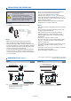
PRECAUTIONS FOR PROPER USE
Never use this product as a sensing device
•
for personnel protection.
In case of using sensing devices for
•
personnel protection, use products which
meet laws and standards, such as OSHA,
ANSI or IEC etc., for personnel protection
applicable in each region or country.
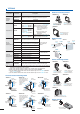
Mounting
The tightening torque should be 0.5 N·m or less.
•
Sensor
mounting
bracket
(Optional)
M3 (length 12 mm 0.472 in)
screw with washers
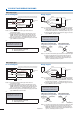
Wiring
Make sure that the power supply is off while wiring.
•
Take care that wrong wiring will damage the sensor.
•
Verify that the supply voltage variation is within the rating.
•
If power is supplied from a commercial switching regulator,
•
ensure that the frame ground (F.G.) terminal of the power
supply is connected to an actual ground.
In case noise generating equipment (switching regulator,
•
inverter motor, etc.) is used in the vicinity of this product,
connect the frame ground (F.G.) terminal of the equipment
to an actual ground.
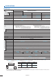
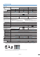
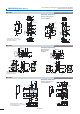
Notes: 1) Not incorporated on the emitter and the basic type sensor.
2) It is the power indicator (green) on the emitter.
3) Not incorporated on the emitter.
4) Basic type: 0.5 m
1.640 ft long.
Notes: 1)
Not incorporated on the emitter.
2) It is the power indicator (green) on the emitter.
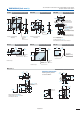
2.3
0.091
3
0.118
3.95 0.156
7.85 0.309
11.8
0.465
Beam
axis
11.2
0.441
Operation indicator (Orange)(Note 2)
Stability indicator (Green)(Note 3)
Sensitivity adjuster (Note 1)
Operation mode switch (Note 1)
3-core (emitter: 2-core)×0.2 mm
2
insulator diameter: ø1.2 ø0.047
15.5 0.610
ø3.7 ø0.146 cable,
2 m
6.562 ft long (Note 4)
2-M3×0.5
0.020
thru-hole threads
()
20
0.787
31
1.220
25.4
1.000
Operation indicator (Orange)(Note 2)
Sensitivity adjuster (Note 1)
3.95 0.156
7.85 0.309
11.8
0.465
2.3
0.091
3
0.118
31
1.220
Stability indicator (Green)(Note 1)
Beam
axis
11.2
0.441
ø9.4
ø0.370
Operation mode switch (Note 1)
M8 connector
2-M3×0.5 0.020
thru-hole threads
20
0.787
( )
42.5
1.673
25.4
1.000
15.5
0.610
35.5
1.398
DIMENSIONS (Unit: mm in)
The CAD data in the dimensions can be downloaded from the website:
panasonic-electric-works.net/sunx
CX-41
Sensor
CX-41-Z
Sensor
18/07/2011