
Datasheet

FIBER
SENSORS
LASER
SENSORS
PHOTO-
ELECTRIC
SENSORS
MICRO
PHOTO-
ELECTRIC
SENSORS
AREA
SENSORS
SAFETY
COMPONENTS
PRESSURE
SENSORS
INDUCTIVE
PROXIMITY
SENSORS
PARTICULAR
USE
SENSORS
SENSOR
OPTIONS
WIRE-
SAVING
SYSTEMS
MEASURE-
MENT
SENSORS
STATIC
CONTROL
DEVICES
LASER
MARKERS
PHOTO-
ELECTRIC
SENSORS
Selection
Guide
Amplifier
Built-in
EX-10
CX-400
EX-20
EX-30
EX-40
EQ-30
EQ-500
MQ-W
RX-LS200
RX
CY
PX-2
RT-610
Amplifier-
separated
Power Supply
Built-in
NX5
VF
SU-7 / SH
SS-A5 / SH
Other
Products
CX-400
Amplier
Built-in
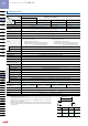
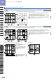
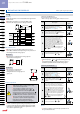
Compact Photoelectric Sensor CX-400 SERIES
250
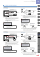
Notes: 1) Not incorporated on the emitter.
2) It is the power indicator (green) on the emitter.
Sensor
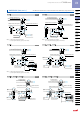
CX-41□
Sensor
CX-41□-Z
Notes: 1) Not incorporated on the emitter.
2) It is the power indicator (green) on the emitter.
2.5
0.098
3
0.118
3.95 0.156
7.85 0.309
11.9
0.469
Beam
axis
11.2
0.441
Operation indicator (Orange)(Note 2)
Stability indicator (Green)(Note 1)
Sensitivity adjuster (Note 1)
Operation mode switch (Note 1)
15.5 0.610
ø3.7 ø0.146 cable,
2 m 6.562 ft long
25.4
1.000
2-M3 × 0.5 0.020
thru-hole threads
( )
20
0.787
31
1.220
Operation indicator (Orange)(Note 2)
Sensitivity adjuster (Note 1)
3.95 0.156
7.85 0.309
11.9
0.469
2.5
0.098
3
0.118
42.5
1.673
35.5
1.398
31
1.220
25.4
1.000
15.5
0.610
Stability indicator (Green)(Note 1)
Beam
axis
11.2
0.441
ø9.4
ø0.370
Operation mode switch (Note 1)
M8 connector
2-M3 × 0.5 0.020
thru-hole threads
20
0.787
( )
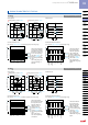
Sensor
CX-41□-J
Notes: 1) Not incorporated on the emitter.
2) It is the power indicator (green) on the emitter.
3.95 0.156
7.85 0.309
11.9
0.469
Operation indicator (Orange)(Note 2)
Stability indicator (Green)(Note 1)
Sensitivity adjuster (Note 1)
Operation mode switch (Note 1)
3
0.118
2.5
0.098
M12 connector
31
1.220
25.4
1.000
15.5 0.610
ø3.7 ø0.146 cable
Beam
axis
11.2
0.441
2-M3 × 0.5 0.020
thru-hole threads
300
11.811
( )
( )
( )
44
1.732
20
0.787
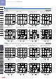
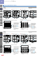
Sensor
CX-49□ CX-48□ CX-42□
3.95 0.156
7.85 0.309
11.9
0.469
Operation indicator (Orange)
Stability indicator (Green)
Sensitivity adjuster
Operation mode switch
4 0.157
2.5
0.098
3
0.118
11.2
0.441
Beam-receiving
part
15.5 0.610
Center of
sensing
25.4
1.000
4
0.157
Beam-emitting
part
2-M3 × 0.5 0.020
thru-hole threads
ø3.7 ø0.146 cable,
2 m 6.562 ft long
31
1.220
20
0.787
( )
Sensor
CX-49□-Z CX-48□-Z CX-42□-Z
( )
3
0.118
2.5
0.098
11.9
0.469
7.85 0.309
3.95 0.156
Sensitivity adjuster
Operation indicator (Orange)
Stability indicator (Green)
Operation mode switch
25.4
1.000
15.5 0.610
2-M3 × 0.5 0.020
thru-hole threads
Center of
sensing
M8 connector
11.2
0.441
ø9.4
ø0.370
Beam-emitting
part
Beam-receiving
part
4
0.157
4
0.157
42.5
1.673
20
0.787
35.5
1.398
31
1.220
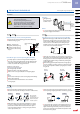
Sensor
CX-49□-J CX-48□-J CX-42□-J
( )
2.5
0.098
20
0.787
11.9
0.469
7.85 0.309
3.95 0.156
Operation mode switch
Sensitivity adjuster
Operation indicator (Orange)
Stability indicator (Green)
Center of
sensing
2-M3 × 0.5 0.020
thru-hole threads
Beam-emitting
part
Beam-receiving
part
15.5 0.610
4 0.157
4
0.157
11.2
0.441
3
0.118
ø3.7 ø0.146 cable
M12 connector
( )
44
1.732
( )
300
11.811
31
1.220
25.4
1.000
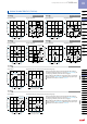
DIMENSIONS (Unit: mm in)
The CAD data in the dimensions can be downloaded from the SUNX website: http://www.sunx.com