Operating Instructions Intelligent Controller Model No. CZ-256ESMC1U Before operating the unit, read these operating instructions thoroughly and keep them for future reference. 85464609160011 CZ-256ESMC1U_改.
CZ-256ESMC1U INTELLIGENT CONTROLLER Operating Instructions CZ-256ESMC1U_改.
CONTENTS 1 IMPORTANT SAFETY INSTRUCTIONS ...................................................................................4 2 FEATURES OF THE SYSTEM ..................................................................................................8 3 SYSTEM CONFIGURATION......................................................................................................9 4 NAMES AND FUNCTIONS OF PARTS ...................................................................................
6.8 Auxiliary Settings ..............................................................................................................53 6.8.1 Registering zone names...........................................................................................53 6.8.2 Setting zone numbers and management targets .....................................................54 6.8.3 Programming timers .................................................................................................56 6.8.3.
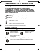
1 IMPORTANT SAFETY INSTRUCTIONS Before using the system, be sure to read these “Important Safety Instructions”. The precautions given in this manual consist of specific “ Warnings” and “ Cautions”. They provide important safety related information and are important for your safety, the safety of others, and trouble-free operation of the system. Be sure to strictly observe all safety procedures. ● The labels and their meanings are as described below.
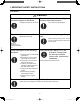
1 IMPORTANT SAFETY INSTRUCTIONS Location Caution Do not install in damp locations or locations subject to vibrations Do not install under direct sunlight or in places near heat sources Damage to the product can result. The product may be damaged. Do not install near sources of noise Avoid static electricity during cabling Malfunctions can result. work Before starting cabling work, touch ground to discharge static electricity from the body.
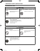
1 IMPORTANT SAFETY INSTRUCTIONS Precautions for Use Warning Do not touch switches with wet hands Protect the Intelligent Controller from water Electric shock and damage to the system can result. Damage to the system can result. Prohibited Prohibited Stop the system and turn the power off if you sense unusual smells or other irregularities Turn off the power. Continuing operation when the system is out of order can result in electric shock, fire, and damage to the system.
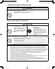
1 IMPORTANT SAFETY INSTRUCTIONS Caution Use the special supplied touch pen Touching the touch panel with any pen other than the supplied touch pen can damage the system. Prohibited Moving and Repair Precautions Warning Do not disassemble or repair Never disassemble or repair the system yourself. Contact your dealer for repair. Electric shock or fire may result if an inexperienced person attempts to repair the system.
2 FEATURES OF THE SYSTEM The Intelligent Controller is a centralized air conditioning management system dedicated to PAC and GHP for small and medium sized buildings. ● Number of connectable units ········ • By connecting communication adaptors to one Intelligent Controller, up to 256 indoor units can be connected. • Up to 120 outdoor units can be connected. ● Display ·········································· • Touch panel type 6.
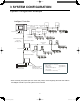
3 SYSTEM CONFIGURATION System Configuration Example Intelligent Controller Indoor/outdoor control wire Link system (non-polar) No.1 Link system No.2 Pulse meter x 3 All-unit signal x 4 Indoor/outdoor control wire (non-polar) Communication adaptor control wire Communication adaptor (RS-485, polar) Link system No.3 Pulse meter x 3 All-unit signal x 4 Link system No.
4 NAMES AND FUNCTIONS OF PARTS ● Front Panel Touch panel type color LCD display Displays operating screens. Use the supplied touch pen to operate. Power indicator lights to show that the intelligent controller is powered on. POWER Touch pen Used to carry out operations on the LCD display. PC Card and touch pen storage cover Push the cover to open it. The compartment inside is used to store the touch pen and to insert and eject PC Cards for backup.
4 NAMES AND FUNCTIONS OF PARTS ● Rear Panel 11 CZ-256ESMC1U_改.
4 NAMES AND FUNCTIONS OF PARTS ● Right side panel Power connector panel AC100V-240V power connector panel. Power switch Powers the Intelligent Controller on and off. OFF ON Communications connector panel 1 2 3 U1 4 U2 5 U1 6 U2 ADAPT Connect to (RS-485) communication adaptor. LINK1 Indoor/outdoor control wire 1 LINK2 Indoor/outdoor control wire 2 7 DO-COMM 8 DO 1 All alarm output 9 DO 2 All operation output 10 DI-COMM 11 DI 1 All stop input 12 DI 2 All start input 12 CZ-256ESMC1U_改.
5 QUICK REFERENCE Menu List Sub Menu 1. Status/Control 1.Each tenant 2.Each tenant details 3.Each zone 4.Each zone details C 5.All units ➢page 31 ➢page 35 ➢page 36 ➢page 37 ➢page 38 2. Total data/Cut-off 1.Each I/D unit 2.Each tenant B 3.Each O/D unit 4.Pulse meter A 5.Cut-off/Data backup ➢page 39 ➢page 40 ➢page 41 ➢page 42 ➢page 43 3. Distrib. ratio/Usage 1.Each I/D unit 2.Each tenant B Main Menu 1.Status/Control 2.Total data/Cut-off 3.Distrib. ratio/Usage 4.Maintenance/Test Run 5.
5 QUICK REFERENCE Menu List Listed are only typical functions. How to operate air conditioners Operating all units collectively desired Operating units individually desired Operating units by tenant desired Operating units by zone desired Varying operation modes desired Varying setting temperatures desired Resetting filter signs desired Varying fan direction and speed Prohibiting remote controlling desired → 6.4.1.3 Operating all connected units → 6.4.1.1 Operating units individually → 6.4.
6 USING THE SYSTEM 6.1 Powering the System On Check the wiring, (air conditioners, communication adaptors, etc.) and then turn the power switch on (see page 12). The system starts automatically. When the system is powered on for the first time, about 10 minutes are required for the normal system screen to appear. Wait until it appears. 6.2 Names and Functions of Screen Parts 6.2.
6 USING THE SYSTEM 6.2.2 Operating screen example The figure below shows a typical operating screen. Filter cleaning sign Main menu This lights when a filter cleaning sign has been issued for an indoor unit. Sub menu 1.Status/Control 2.Total data/Cut-off 3.Distrib. ratio/Usage 4.Maintenance/Test Run 5.Initial settings 6.Auxiliary settings Operate on all units Displays tenant name. Displays unit name. Timer operation mark Scrolls the columns displaying indoor units.
6 USING THE SYSTEM * Selection windows When you touch [Tenant] (or whatever is displayed in blue between the scroll buttons) shown on the previous page, the items available for selection appear in a list as follows, enabling direct selection. [Tenant] list (FRI) 4/Aug 2:56PM A similar list appears for the other buttons. [I/D unit] list [Weekly timer] list Tenant holiday [Date] list 17 CZ-256ESMC1U_改.
6 USING THE SYSTEM 6.3 Initial Settings The items in the “Initial settings” menu (main menu 5) must be set in order to use the Intelligent Controller. Be sure to set these items. Before making the settings, read the following and decide what kind of information you want to obtain from the system. (1) Setting central addresses Central addresses must be set on the “CNTR/Unit/Ten.No.” screen ( Main5 Sub2 ).
6 USING THE SYSTEM 6.3.1 System setting flow : Settings are necessary. : Settings are necessary depending on circumstances. : Settings are unnecessary. Basic settings are completed by setting items of “ ” one by one in accordance with the system management of the customer. Items of “ ” need to be set only when making necessary settings and maintenance upon customer request regardless of the said management. Air conditioner operation only START ↓ 5 Sub1 Date/Distrib.
6 USING THE SYSTEM ↓ 5 Sub5 Clear accum.data Main Note 6 ↓ Air conditioner operation only Displaying distribution ratios (simple distribution) Displaying distribution ratios (loaded distribution) Displaying energy usage (simple distribution) Displaying energy usage (loaded distribution) Note 1 6 Sub1 Zone name Note 7 Main ↓ 6 Sub2 ZoneNo./Mng.target Main (1) Zone No. (2) Management target ↓ Note 7 6 Sub3 Program timer Main (1) Daily timer (2) Weekly timer ↓ 6 Sub4 Main Ten.
6 USING THE SYSTEM Air conditioner operation only ↓ Main6 Sub10 WEB settings Note 17 Displaying distribution ratios (simple distribution) Displaying distribution ratios (loaded distribution) Displaying energy usage (simple distribution) Displaying energy usage (loaded distribution) ↓ Main6 Sub11 User settings Note 17 ↓ Main 2 Sub5 Cut-off/Data backup (1) Manual cut-off (2) Data backup (3) Restore ↓ END Note 1 Note 2 Note 3 Note 4 Note 5 Note 6 Note 6 Note 13 Note 13 and 16 Settings are necessa
6 USING THE SYSTEM 5 Sub1 Main 6.3.2 Setting the date, cut-off date, and distribution ratio calculation method Use this screen to set the current date and time, and make settings related to time. These settings are needed for program timers and distribution ratio calculation, so be sure to make them before starting operation of the system. Procedure Select 5.Initial settings in the main menu and 1.Date/Distrib. in the sub menu, then proceed as follows. A Set the current date and time.
6 USING THE SYSTEM 5 Sub1 Main C Select the calculation target of power distribution. (3) Select T/S ON+OFF time , T/S ON time , or No Distrib. . - T/S ON + OFF time To be selected when taking power both for the outdoor and indoor units to make distribution calculation. - T/S ON time To be selected when taking power only for the outdoor unit to make distribution calculation. - No Distrib. To be selected when distribution calculation for gas and electricity is unnecessary.
5 Sub2 6 USING THE SYSTEM Main 6.3.3 Setting central addresses, unit names and tenant numbers Use this screen to set central addresses, names of units connected to the system and tenant numbers. Procedure Select 5.Initial settings in the main menu and 2.CNTR/Unit/Ten. No. in the sub menu, then proceed as follows. 1.Status/Control 2.Total data/Cut-off 3.Distrib. ratio/Usage 4.Maintenance/Test Run 5.Initial settings 6.Auxiliary settings A B 1.Date/Distrib. 2.CNTR/Unit/Ten. No. 3.Ten. name/Distrib. Gr.
6 USING THE SYSTEM 5 Sub2 Main B Touch an unit name column. A keyboard window like the one shown below appears. Use the keyboard to enter an unit name. Unit names can be up to 12 characters long. * See “7 ENTERING TEXT AND NUMBERS” for details about entering text in keyboard windows. * You can copy and paste text using the [Copy] and [Paste] buttons. See “7.2 Entering Text” for details. C Touch a tenant number.A keyboard window like the one shown below appears.
6 USING THE SYSTEM 5 Sub3 Main 6.3.4 Setting tenant names and distribution groups Use this screen to set tenant names and distribution groups. You can also use this screen to set the product type (PAC, GHP, HOT, etc.) of indoor units. Procedure Select 5.Initial settings in the main menu and 3.Ten. name/Distrib. Gr. in the sub menu, then proceed as follows. 1.Status/Control 2.Total data/Cut-off 3.Distrib. ratio/Usage 4.Maintenance/Test Run 5.Initial settings 6.Auxiliary settings 1.Date/Distrib. 2.
6 USING THE SYSTEM 5 Sub3 Main B Touch a distribution group. A keyboard window like the one shown above appears. Use the keyboard to enter a distribution group number and to select the product type from among PAC, GHP and HOT. Select “Simple” or “Load” in the distribution methods. * Refer to “10. Calculating air conditioner distribution” for details. The tenant set at “Load” distribution will have its “No” box display in light blue. * The distribution group number range is from 1 to 8.
6 USING THE SYSTEM 5 Sub 4 Main 6.3.5 Making pulse meter settings If you have connected pulse meters, use this screen to set the target distribution groups and the amount of electricity or gas per pulse. Procedure Select 5. Initial settings in the main menu, and 4. Pulse meter setting in the sub menu. 1.Status/Control 2.Total data/Cut-off 3.Distrib. ratio/Usage 4.Maintenance/Test Run 5.Initial settings 6.Auxiliary settings 1.Date/Distrib. 2.CNTR/Unit/Ten. No. 3.Ten. name/Distrib. Gr. 4.
6 USING THE SYSTEM 5 Sub 4 Main F Select this check box for ice heat accumulation night power meters. (Enabled during loaded distribution setting only.) * This cannot be set for electricity meters configured for use with HOT Multi or simple distribution. G For the night power meter set in F, select which outdoor system to meter ice heat accumulation by selecting the address. 29 CZ-256ESMC1U_改.
6 USING THE SYSTEM 5 Sub5 Main 6.3.6 Clear accumulation data Use this screen to erase total data after test runs, and to restart total calculations for operating time, operating counts, and so on. Procedure Select 5.Initial settings in the main menu and 5.Clear accum. data in the sub menu, then proceed as follows. 1.Status/Control 2.Total data/Cut-off 3.Distrib. ratio/Usage 4.Maintenance/Test Run 5.Initial settings 6.Auxiliary settings 1.Date/Distrib. 2.CNTR/Unit/Ten. No. 3.Ten. name/Distrib. Gr. 4.
6 USING THE SYSTEM 1 Sub1 Main 6.4 Status Monitoring and Operation Screens 6.4.1 Displaying general information by tenant Use this screen to display information about all connected indoor units by tenant. Procedure Select 1.Status/Control in the main menu and 1.Each tenant in the sub menu. The indoor units for each tenant are displayed. 1.Status/Control 2.Total data/Cut-off 3.Distrib. ratio/Usage 4.Maintenance/Test Run 5.Initial settings 6.Auxiliary settings 1.Each tenant 2.Each tenant details 3.
6 USING THE SYSTEM 1 Sub1 Main 6.4.1.1 Operating units individually Use this screen to operate individual indoor units. Procedure Select 1.Status/Control in the main menu and 1.Each tenant in the sub menu. A When you touch the unit that you want to set, a remote control window for individual on/off operations appears. B When you touch , a remote control window appears. This window allows you to make detailed settings for operations on individual units. 1.Status/Control 2.Total data/Cut-off 3.Distrib.
6 USING THE SYSTEM 1 Sub1 Main 6.4.1.2 Operating all units by tenant Use this screen to operate all connected indoor units of each tenant. Procedure Select 1.Status/Control in the main menu and 1.Each tenant in the sub menu. A When you touch a tenant name, a remote control window appears. This window allows you to perform on/off operations for all units of the tenant. B When you touch , a remote control window appears.
6 USING THE SYSTEM 1 Sub1 Main 6.4.1.3 Operating all connected units Use this screen to operate all connected indoor units. Procedure Select 1.Status/Control in the main menu and 1.Each tenant in the sub menu. A When you touch All units , a remote control window appears. This window allows you to perform on/off operations for all connected units. B When you touch , a remote control window appears. This window allows you to make detailed settings for all connected units. 1.Status/Control 2.
6 USING THE SYSTEM 1 Sub 2 Main 6.4.2 Displaying detailed information by tenant Use this screen to display detailed settings and operating for each tenant. Procedure Select 1.Status/Control in the main menu and 2.Each tenant details in the sub menu. A When you touch a unit name, a remote control window for individual operations appears. B When you touch a tenant name, a remote control window for operating all tenant units appears.
6 USING THE SYSTEM 1 Sub 3 Main 6.4.3 Displaying general information by zone Use this screen to display the state of all units in a zone and to operate those units. Procedure Select 1.Status/Control in the main menu and 3.Each zone in the sub menu. A When you touch a unit name, a remote control window for individual operations appears. B When you touch a zone name, a remote control window for operating all units in the zone appears.
6 USING THE SYSTEM 1 Sub 4 Main 6.4.4 Displaying detailed information by zone Use this screen to display detailed settings and operating for each zone. Procedure Select 1.Status/Control in the main menu and 4.Each zone details in the sub menu. A When you touch a unit name, a remote control window for individual operations appears. B When you touch a zone name, a remote control window for operating all units in the zone appears.
6 USING THE SYSTEM 1 Sub 5 Main 6.4.5 Displaying and operating all indoor units Use this screen to display information about the state of all indoor units and to operate all indoor units at once. Procedure Select 1.Status/Control in the main menu and 5.All units in the sub menu. One screen displays up to 100 indoor units in order of their tenant. The units can be operated individually or all at once. A When you touch a unit name, a remote control window for individual operations appears.
6 USING THE SYSTEM Main 2 Sub1 6.5 Total Data and Manual Cut-Off Processing 6.5.1 Displaying total data by indoor unit Use this screen to check total data such as the operating time and the number of operations for each indoor unit. Procedure Select 2.Total data/Cut-off in the main menu and 1.Each I/D unit in the sub menu. A Selects the tenant to display. B Selects either the current or the past (maximum 24 months) cut-off data. C Selects the time zone to display.
6 USING THE SYSTEM Main 2 Sub2 6.5.2 Displaying total data by tenant Use this screen to check total data such as the operating time and the number of operations for each tenant. Procedure Select 2.Total data/Cut-off in the main menu and 2.Each tenant in the sub menu. A Selects the distribution group to display. B Selects either the current or the past (maximum 24 months) cut-off data. C Selects the time zone to display. 5 Sub1 ) * This button will be invalid when setting the mode at “No Distrib.”.
6 USING THE SYSTEM Main 2 Sub3 6.5.3 Displaying total data by outdoor unit Use this screen to check total data such as the operating time and the number of operations for each outdoor unit. Procedure Select 2.Total data/Cut-off in the main menu and 3.Each O/D unit in the sub menu. A Selects the connection destination link system to display. B Selects either the current or the past (maximum 24 months) cut-off data. 1.Status/Control 2.Total data/Cut-off 3.Distrib. ratio/Usage 4.Maintenance/Test Run 5.
6 USING THE SYSTEM Main 2 Sub 4 6.5.4 Displaying pulse meter total data Use this screen to check the pulse count and other such cumulative data for pulse meters. Procedure Select 2. Total data/Cut-off in the main menu, and 4. Pulse meter in the sub menu. A Selects the pulse meter connection destination. B Selects either the current or the past (maximum 24 months) cut-off data. C Selects the time zone to display. 5 Sub1 ) * This button will be invalid when setting the mode at “No Distrib.”.
6 USING THE SYSTEM Main 2 Sub5 6.5.5 Performing manual cut-off processing and saving data Use this screen to perform manual cut-off processing, and to back up setting and total data to optional PC Cards. 6.5.5.1 Manual cut-off processing Proceed as follows to manually perform cut-off processing. Procedure Select 2.Total data/Cut-off in the main menu and 5.Cut-off/Data backup in the sub menu. A Touch Cut-off . 1.Status/Control 2.Total data/Cut-off 3.Distrib. ratio/Usage 4.Maintenance/Test Run 5.
6 USING THE SYSTEM Main 2 Sub5 6.5.5.2 Saving data Proceed as follows to back up setting data and totals data to optional PC Cards. Procedure Complete the cut-off processing described in “6.5.5.1 Manual cut-off processing” and then execute the following backup procedure. D Insert a PC card and touch the Backup button. E When a window like the one shown below F When a window like the one shown below appears, touch the Check button. appears, touch the OK button.
6 USING THE SYSTEM Main 2 Sub5 I When a screen like the one shown below appears, touch the Check button. [File form] A file name is fixed as follows according to the year, month, and date when the distribution data output was carried out. 20060316A.csv (Example of a file output on March 16, 2006) When outputting repeatedly on the same day, the last “A” varies as B, C, D, and so forth. (Outputting is possible up to 26 times a day).
6 USING THE SYSTEM Main 3 Sub1 6.6 Air Conditioning Distribution Ratios and Energy Usage 6.6.1 Displaying distribution ratios and energy usage by indoor unit Use this screen to check the distribution ratios and energy usage of indoor units. Procedure Select 3.Distrib. ratio/Usage in the main menu and 1.Each I/D unit in the sub menu. 5 Sub1 ) *When “No Distrib.” is selected, this screen is not accessible. (see Main A Selects the tenant to display.
6 USING THE SYSTEM 3 Sub2 Main 6.6.2 Displaying distribution ratios and energy usage by tenant Use this screen to check the distribution ratios and energy usage by tenant. Procedure Select 3.Distrib. ratio/Usage in the main menu and 2.Each tenant in the sub menu. 5 Sub1 ) *When “No Distrib.” is selected, this screen is not accessible. (see Main A Selects the distribution group to display. B Selects either the current or the past (maximum 24 months) cut-off data. C Selects the time zone to display.
6 USING THE SYSTEM 6.6.3 Time zone totals and distribution The Intelligent Controller provides functions for recording total operating time and calculating distribution ratios for four time zones: All hours, Regular hours, Out of hours, and Special days. When using these functions, be aware of the following points. ■ Margin of error in time zone operating totals The intelligent controller acquires operating time data accumulated by individual indoor units via communication adaptors.
6 USING THE SYSTEM 4 Sub1 Main 6.7 Maintenance and Test Runs 6.7.1 Checking inspection signs Use this screen to check for indoor units for which filter cleaning signs have been issued, and outdoor units (GHP) for which engine oil inspection signs have been issued. Procedure Select 4.Maintenance/Test Run in the main menu and 1.Inspection sign in the sub menu.
6 USING THE SYSTEM 4 Sub 2 Main 6.7.2 Checking the alarm logs Use this screen to check logs of up to the past 14 alarms and errors for individual indoor units. Procedure Select 4.Maintenance/Test Run in the main menu and 2.Alarm log in the sub menu. A Select the tenant to display. B Select the indoor unit to display. 1.Status/Control 2.Total data/Cut-off 3.Distrib. ratio/Usage 4.Maintenance/Test Run 5.Initial settings 6.Auxiliary settings 1.Inspection sign 2.Alarm log 3.
6 USING THE SYSTEM 4 Sub 2 Main D Select “I/D alarm log”, “O/D comm. error log”, or “Adaptor alarm log”. [O/D comm. error log] logs the history of errors in communication between the outdoor unit and the Intelligent Controller or the communication adaptor. D (WED)21/Apr 5:56PM [Adaptor alarm log] logs the history of warnings as determined by the Intelligent Controller or the communication adaptor. (Duplicate adaptor addresses, communication error between the Intelligent Controller and adaptor, etc.
4 Sub 3 6 USING THE SYSTEM Main 6.7.3 Executing test runs Use this screen to display list of each indoor unit for outdoor unit system addresses. You can execute test runs , either for each outdoor unit system address or individually. Procedure Select 4.Maintenance/Test Run in the main menu and 3.Test run in the sub menu. A Select a connection destination link system. B Select the outdoor unit to operate. 1.Status/Control 2.Total data/Cut-off 3.Distrib. ratio/Usage 4.Maintenance/Test Run 5.
6 USING THE SYSTEM 6 Sub1 Main 6.8 Auxiliary Settings 6.8.1 Registering zone names You can assign names to zones. Zones are unrelated to distribution, so you can mix GHP, PAC, and HOT units, and make settings that extend across link systems. Start/stop, monitoring, timer operation and so on can be done all at once for all units in a zone. Procedure Select 6.Auxiliary settings in the main menu and 1.Zone name in the sub menu. 1.Status/Control 2.Total data/Cut-off 3.Distrib. ratio/Usage 4.
6 USING THE SYSTEM 6 Sub2 Main 6.8.2 Setting zone numbers and management targets Use this screen to set the zone number and management category for individual indoor units. Be sure to assign a central address to each unit. Procedure Select 6.Auxiliary settings in the main menu and 2.ZoneNo./Mng.target in the sub menu. 1.Status/Control 2.Total data/Cut-off 3.Distrib. ratio/Usage 4.Maintenance/Test Run 5.Initial settings 6.Auxiliary settings 1.Zone name 2.ZoneNo./Mng.target 3.Program timer 4.Ten.
6 USING THE SYSTEM 6 Sub2 Main A A window like the one shown at right appears when you touch the zone number column. Enter digits specify to the zone number. * Zone No. can be registered in the range 1 to 128. B A window like the one shown at right appears when you touch the management column. Select one from among Target, Individual operation, or Not Target.
6 USING THE SYSTEM 6 Sub3 Main 6.8.3 Programming timers Up to 50 types of daily timers and 50 types of weekly timers can be programmed. It is also possible to set holidays or timer special days for tenants. 6.8.3.1 Programming daily timers Up to 50 types of daily timers can be programmed, with up to 50 times per day. Start/stop, operation mode, temperature settings, and remote control prohibition can be programmed. Procedure Select 6.Auxiliary settings in the main menu and 3.
6 USING THE SYSTEM 6 Sub3 Main D Touch Set to confirm the time. E Touch Cancel to cancel the setting. The display changes to “—”. F Touch the Start/Stop column and set in the following window. Closes the window. Programs the timer to start the unit. Programs the timer to stop the unit. Cancels the setting. Confirms the setting. G Touch the Op mode column and set in the following window. Closes the window. Sets the operating mode. Select from among Heat, Cool, Fan, Dry, and Auto.
6 USING THE SYSTEM 6 Sub3 Main H Touch the Set temp. column and set in the following window. Closes the window. Lowers the temperature. Raises the temperature. Cancels the setting. Confirms the setting. I Touch the Prhbt R/C column and set in the following window. Closes the window. Switches between Prohibit1, Prohibit2, Prohibit3, Prohibit4, and Accept. Displays a window that allows you to check prohibit status. Confirms the setting. Cancels the setting.
6 USING THE SYSTEM 6 Sub3 Main 6.8.3.2 Programming weekly timers You can program weekly timers by assigning any daily timer to each day of the week. Up to 50 types of weekly timers can be programmed. Procedure Select 6.Auxiliary settings in the main menu and 3.Program timer in the sub menu. 1.Status/Control 2.Total data/Cut-off 3.Distrib. ratio/Usage 4.Maintenance/Test Run 5.Initial settings 6.Auxiliary settings 1.Zone name 2.ZoneNo./Mng.target 3.Program timer 4.Ten.Ho/TimerSp.Day 5.Prohibit R/C 6.
6 USING THE SYSTEM 6 Sub4 Main 6.8.4 Setting Tenant holiday/Timer special day You can make settings by tenant of days of setting timer for holidays and timer special days. Holidays and timer special days can be registered for up to the next two years. Procedure Select 6.Auxiliary settings in the main menu and 4.Ten.Ho/Timer Sp. Day in the sub menu. 1.Status/Control 2.Total data/Cut-off 3.Distrib. ratio/Usage 4.Maintenance/Test Run 5.Initial settings 6.Auxiliary settings 1.Zone name 2.ZoneNo./Mng.
6 USING THE SYSTEM 6 Sub5 Main 6.8.5 Prohibiting remote control use You can prohibit the use of the remote controls connected to indoor units. Procedure Select 6.Auxiliary settings in the main menu and 5.Prohibit R/C in the sub menu. 1.Status/Control 2.Total data/Cut-off 3.Distrib. ratio/Usage 4.Maintenance/Test Run 5.Initial settings 6.Auxiliary settings 1.Zone name 2.ZoneNo./Mng.target 3.Program timer 4.Ten.Ho/TimerSp.Day 5.Prohibit R/C 6.Distribution time zone 7.Special distrib. day 8.
6 USING THE SYSTEM 6 Sub6 Main 6.8.6 Setting distribution time zones You can set distribution time zones for the same day of each week. Procedure Select 6.Auxiliary settings in the main menu and 6.Distribution time zone in the sub menu. 5 Sub1 ) *When “No Distrib.” is selected, this screen is not accessible. (see Main 1.Status/Control 2.Total data/Cut-off 3.Distrib. ratio/Usage 4.Maintenance/Test Run 5.Initial settings 6.Auxiliary settings 1.Zone name 2.ZoneNo./Mng.target 3.Program timer 4.Ten.
6 USING THE SYSTEM 6 Sub7 Main 6.8.7 Setting special distribution days You can set special distribution days to which normal time zone settings do not apply. Use this function for holidays and so on. Special distribution days can be registered for up to the next two years. Procedure Select 6.Auxiliary settings in the main menu and 7.Special distrib. day in the sub menu. 5 Sub1 ) *When “No Distrib.” is selected, this screen is not accessible. (see Main 1.Status/Control 2.Total data/Cut-off 3.Distrib.
6 USING THE SYSTEM 6 Sub8 Main 6.8.8 Indoor unit settings You can use this screen to check the air conditioning capacity of indoor units, and to set the capacity. Normally you do not need to change settings with this screen. Exercise care when changing settings, because improper settings can prevent accurate distribution. Procedure Select 6.Auxiliary settings in the main menu and 8.I/D unit settings in the sub menu. 5 Sub1 ) *When “No Distrib.” is selected, this screen is not accessible. (see Main 1.
6 USING THE SYSTEM 6 Sub9 Main 6.8.9 Other settings You can use this screen to register passwords, initialize data, and make power saving settings for the LCD display. Procedure Select 6.Auxiliary settings in the main menu and 9.Other settings in the sub menu. 1.Status/Control 2.Total data/Cut-off 3.Distrib. ratio/Usage 4.Maintenance/Test Run 5.Initial settings 6.Auxiliary settings 1.Zone name 2.ZoneNo./Mng.target 3.Program timer 4.Ten.Ho/TimerSp.Day 5.Prohibit R/C 6.Distribution time zone 7.
6 USING THE SYSTEM 6 Sub9 Main 6.8.9.2 Registering passwords B Click the Not registered button to display a keyboard window for registering passwords. You can register 3 kinds of passwords: “Setting”, “Distrib.”, and “Operation”. Refer to “Menu list” under “5. Quick reference” for details. Enter a 4-digit number from 0000 to 9999, and touch the Set button. The caption on the Not registered button changes to Registered . To delete a password, first enter the four-digit password, then touch the Set button.
6 USING THE SYSTEM 6 Sub9 Main 6.8.9.6 LCD auto off settings F The auto display off settings allow you to select a time after which the LCD display should be automatically turned off if there is no activity. The LCD display is turned on again when you touch it. Settings: 5 minutes, 10 minutes, 15 minutes, 30 minutes, OFF (default: 30 minutes) Turning the LCD display off when it is not in use saves power and can prolong the life of the display and backlight. 6.8.9.
6 USING THE SYSTEM 6 Sub9 Main 6.8.9.8 Power off button H Always touch this button before powering the Intelligent Controller off. A message appears asking if you want to exit the program. Touch OK in the message. The system saves current data, and then displays a message “It is now safe to turn off the Intelligent Controller.” Wait until this message appears before powering the system off. (If there is a large amount of data, several minutes may be required for this message to appear.
6 USING THE SYSTEM 6 Sub10 Main 6.8.10 WEB settings Settings related to WEB such as the site name, mail settings, and network settings are possible. Procedure Select 6. Auxiliary settings in the main menu and 10. WEB settings in the sub menu. 1.Status/Control 2.Total data/Cut-off 3.Distrib. ratio/Usage 4.Maintenance/Test Run 5.Initial settings 6.Auxiliary settings 1.Zone name 2.ZoneNo./Mng.target 3.Program timer 4.Ten.Ho/TimerSp.Day 5.Prohibit R/C 6.Distribution time zone 7.Special distrib. day 8.
6 Sub10 6 USING THE SYSTEM Main K Input the IP address of the primary and secondary DNS servers as necessary. L Input the IP address of the primary and secondary WINS servers as necessary. M Input the Intelligent Controller’s device name (device ID) (within 15 characters). (This is used to identify the Intelligent Controller when using DNS, for example.) N For details on the mail server settings, see “6.8.10.1 Detailed server settings”.
6 Sub10 6 USING THE SYSTEM Main D Select this option if you want to perform SMTP authentication during mail transmission. Settings E and F below are valid only when you have selected SMTP authentication. E Select either or all of the authentication methods: “LOGIN”, and “PLAIN”. If both check boxes are selected, “LOGIN” takes priority. If both check boxes are not selected, then SMTP authentication is not performed. F Specify a user ID and a password for authentication.
6 Sub11 6 USING THE SYSTEM Main 6.8.11 User settings The user ID, password, authority, and operatable tenant can be set. Procedure Select 6.Auxialiary settings in the main menu and 11.User settings in the sub menu. 1.Status/Control 2.Total data/Cut-off 3.Distrib. ratio/Usage 4.Maintenance/Test Run 5.Initial settings 6.Auxiliary settings 1.Zone name 2.ZoneNo./Mng.target 3.Program timer 4.Ten.Ho/TimerSp.Day 5.Prohibit R/C 6.Distribution time zone 7.Special distrib. day 8.I/D unit settings 9.
6 Sub11 6 USING THE SYSTEM Main For items A and B, touch each input box and a soft keyboard will appear. A Input an optional user ID (within 20 characters). B Input an optional password (within 10 characters). C Users include three categories: “Administrator”, “Special user”, and “General user”. No. 000 denotes “Administrator” (A special user solely admitted; its initial user ID: administrator). No.001 or higher denotes “Special user” if authority is set to , and “General user” if authority is set to .
6 USING THE SYSTEM 6.9 System Configuration Changes An alarm message like the following appears when a system configuration change (or the possibility of a configuration change) is detected. If the system continues to operate after its configuration has changed, distribution ratios and other data will be totally inaccurate. For this reason, cut-off processing must be done with the system in the state before the change. The following message is displayed to ask you to confirm the processing.
6 USING THE SYSTEM 6.9.2 When system configuration may change This alarm message is displayed in cases such as the following. A The following “Detailed settings” were made from a local remote controller. (for address, extension settings, indoor unit capacity, or presence/abesnce of an electric heater) B Only confirmation of “Detailed setting” was made from a local remote controller. C Automatic address setting was carried out for an indoor or outdoor unit.
7 ENTERING TEXT AND NUMBERS This system displays keyboard and numeric keypad windows when you need to enter names and numbers. The numeric keypad window appears when you need to enter numbers, and the keyboard window appears when you need to enter text. 7.1 Entering Numbers A numeric keypad window like the one shown below appears when you need to enter a number, for example to register a password. A B C D E A Input field Displays the number being entered.
7 ENTERING TEXT AND NUMBERS 7.2 Entering Text A keyboard window like the one shown below appears when you need to enter text, for example a tenant name. To edit an existing text string, touch the character that you want to edit in the input field. Alphanumeric, lowercase L A M B C K D E F G H IJ A Input field Displays the text being entered. B Information field Displays information about the target of the operation (for example, the tenant number when a tenant name is being entered).
7 ENTERING TEXT AND NUMBERS H DEL button Deletes the character to the right of the input cursor. I BS button Deletes the character to the left of the input cursor. J Set button Enables the entered character string. K Close button Closes the keyboard window. L Copy button Copies text displayed in the input field. You can also copy portions of the text by dragging the touch pen over the desired portion.
8 CONNECTION OF EXTERNAL SIGNALS When connecting external signals, refer to the Installation Instructions (end of this manual) for detailed information about the electrical specifications. 8.1 Pulse Meter Input You can measure energy usage by connecting pulse meters (gas, fuel, and electricity meters). If you do not need to view information about energy usage, there is no need to install pulse meters.
8 CONNECTION OF EXTERNAL SIGNALS 8.2 All Stop Input You can stop all connected units automatically by connecting external signals (for example, from fire-alarm detectors.) All stop input is available only for managed (“target”) units. It does not affect units which have been designated as not managed (“Not target”) or individually operated (“Indiv Op”).
8 CONNECTION OF EXTERNAL SIGNALS 8.4 All-Unit Alarm Output An external signal is output when an alarm or error occurs in any connected unit. This signal can be used by alarm monitors and other equipment. 1) Output location The communications connector panel on the side of the Intelligent Controller or on an optional communication adaptor connected to the Intelligent Controller: DO1, DO-COMM 2) Operation The signal goes ON when an alarm or error occurs, and goes OFF when normal status is restored. 8.
9 TERMS This section explains some of the terms used in this manual. ■ Adaptor address (No. 0 set on Intelligent Controller, No. 1 to 7 set on communication adaptors) An adaptor address is the address assigned to an optional communication adaptor. ■ Link system address (No. 1 to 2, fixed) A link system is a collection of indoor units and outdoor units connected to a single inter-unit control wire.
10 CALCULATING AIR CONDITIONER DISTRIBUTION The Intelligent Controller calculates energy (electricity and gas) distribution ratios utilizing the accumulated working time (T/S ON/OFF) or the capacity value of the indoor unit. * T/S: Thermostat 10.
10 CALCULATING AIR CONDITIONER DISTRIBUTION Calculate electricity/gas usage index of entire distribution group Let “TOTALe” be the electricity usage index of entire distribution group, and let “TOTALg” be the gas usage index of entire distribution group. Let “m” be the number of indoor units in the distribution group.
10 CALCULATING AIR CONDITIONER DISTRIBUTION 10.
10 CALCULATING AIR CONDITIONER DISTRIBUTION 10.
11 SUPPLEMENTARY INFORMATION-1 IMPORTANT • Microsoft and Windows CE are trademarks of Microsoft Corporation in the United States and other countries. Other products names are trademarks or registered trademarks of their respective holders, or copyrights of their respective holders. • Duplication of all or part of the software and documentation of this product without the express consent of the holder of the rights to the above, and transfer of the software to another party, are prohibited by law.
12 SUPPLEMENTARY INFORMATION-2 ■ Powering the system off Always use the following procedure to power the Intelligent Controller off. Touch the Power off button in the “Other settings” screen ( Main6 Sub9 ). Touch the OK button in the message box which appears to ask if you want to exit the program. Wait until a message appears to inform you that “It is now safe to turn off the Intelligent Controller.” (∗) and then power the system off. (*Several minutes may pass before this message appears.
12 SUPPLEMENTARY INFORMATION-2 ■ Errors occurred while operating during a thunder storm or because of electromagnetic interference. Power the Intelligent Controller off and then on again. (Refer to “Powering the system off” stated on the previous page) As a rule, the Intelligent Controller should be powered off only in cases such as the above. Correct management of air conditioning is not possible when the Intelligent Controller is powered off.
12 SUPPLEMENTARY INFORMATION-2 ■ About Interface adaptors You can use Interface adaptors to connect equipment that can be turned on and off (fans, room air conditioners and so on) to the Intelligent Controller. However, note that the following limitations apply. For details, refer to the documentation of the equipment or contact your dealer or service provider. Central control is supported for the following operations only.
13 TROUBLESHOOTING Before requesting service, check the following items. Do not attempt to service the Intelligent Controller yourself. Doing so can be dangerous. Symptom Cause • Is the power cord connected? • Is the power switch set to on? • Is timer operation set to the target unit? Operation of a selected timer does not start if the setting is not set the target unit. • Does the setting match the current date and time?If the date and time do not match, operation can start at an unexpected time.
13 TROUBLESHOOTING Symptom Cause One of the following messages is displayed • Contact the store where you purchased the system or our and the unit does not start. service agency. • Application error !! • DiskErr • CF error !! A message, “Diskxx access error”, is Press the [Check] button to close, and press [Reset] to the displayed. (xx is a number from 1 to 4) left of the clock display. If the same message appears again, consult your local dealer or service representative. 92 CZ-256ESMC1U_改.
14 MAINTENANCE ■ Unplug the power cord before cleaning the Intelligent Controller. The system has high-voltage connectors and other dangerous components. Always power the system off and unplug the power cord before cleaning it. ■ Use a neutral solvent To clean the control panel and touch panel, use a soft cloth slightly moistened with a neutral solvent. Do not use volatile liquids such as benzene or thinner, and do not use polishing power or pesticides.
15 SPECIFICATIONS Product number CZ-256ESMC1U External dimensions 10-5/8 in. (H) × 17-3/64 in. (W) × 6-9/64 in. (D) Method of installation Front door of control panel Maximum number of connectable units Maximum 128 air conditioners (indoor units) Maximum 256 air conditioners (indoor units) with communication adaptor connected Timer precision ± Approx.
15 SPECIFICATIONS 95 CZ-256ESMC1U_改.
16 INSTALLATION (ELECTRIC) AND SERVICE INSTRUCTIONS Safety Precautions Before conducting installation or electrical work, be sure to carefully read these “Safety Precautions” and follow them carefully. The precautions given in this manual consist of specific “Warnings” and “Cautions”. Be sure to follow these precautions, as they provide important safety related information. The labels and their meanings are as described below.
16 INSTALLATION (ELECTRIC) AND SERVICE INSTRUCTIONS Take the following into consideration when designing the control box: 1. To ensure sufficient airflow for cooling, provide air vents (holes, slots, etc.) on the upper, lower, left and right sides of the box, as shown in the figure below. (Be sure not to clog the ventilation hole when setting.) Ensure that the temperature inside the control box does not exceed 104°F. Control box example 6.0 inch min. air vents (side) 2.0 inch min. 4.0 inch min. 4.
16 INSTALLATION (ELECTRIC) AND SERVICE INSTRUCTIONS 3 Wiring Always shut off the power supply (breaker) before installing or uninstalling. Connection terminals (1) Power supply connection Connect the power supply to the commercial power mains (100 to 240 V AC), using a dedicated circuit. Connect the power supply lines to the L and N power supply terminals (the power supply neutral to the N terminal). Connect an earth ground line to the power supply terminal.
16 INSTALLATION (ELECTRIC) AND SERVICE INSTRUCTIONS 4 Connecting to external equipment (1) External system inputs (no-voltage contact point static) Equipment Equipment Digital inputs Equipment (Output common) stopinput inputDIDI11 AllAllstop All alarm output startinput inputDIDI22 AllAllstart All operation output (reserved) (3) Pulse meter inputs (no-voltage contact point pulse) (2) External system outputs (no-voltage contact point static) DI 3 6 Power switch Gas flow meter (Fuel flow meter)
DC1011-11111 Printed in Japan CZ-256ESMC1U_改.