
Installation Manual


5
(3) Setting the inter-unit control wiring connection on/off
1
Repeat steps
1
to
3
in section (2) “Adaptor number setting procedure” above. The following will display:
(1.Ano.03) (When the adaptor number is 3)
2
Press the
UP
key once so the following display appears:
(2.Adyu.0) (Factory setting)
3
Hold down the
SET
key for at least 1 second so the “0” part blinks, indicating that the setting can be changed. (The green and red monitor
LEDs are both on.)
Use the
UP
and
DOWN
keys to turn the iinter-unit control wiring connection on or off as shown in the table below.
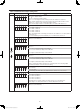
Setting value Inter-unit control wiring connection
0 LINK1: On, LINK2: On (factory setting)
1 LINK1: On, LINK2: Off
2 LINK1: Off, LINK2: On
3 LINK1: Off, LINK2: Off
For example, to connect the inter-unit control wiring only to LINK1, press the
UP
key once. The following display will result:
(2.AdYu.1)
4
Press the
SET
key for at least 1 second to confi rm. (Only the green monitor LED is on.)
(4) Other settings
With the display status showing as in number
3
in section (2) “Adaptor number setting procedure”, press the
UP
and
DOWN
keys to select the
setting items shown in the table below. Set as needed.
The setting procedure is the same as above.
(Press the
SET
key for at least 1 second, press the
UP
and
DOWN
keys to change, then press the
SET
key at least one second to confi rm.)
Note
1
When confi guring, do not set the same adaptor number more than once.
* Use numbers between 1 and 7 for connecting to an Intelligent Controller.
2
Turn the inter-unit control wiring connection on/off as appropriate.
(Set to “Off” for LINKs with no connection.)
3
For connecting the inter-unit control wiring to only one link, use the
“LINK1” side.
Panasonic_CZ-CFUNC1U_Eng.indd 5Panasonic_CZ-CFUNC1U_Eng.indd 5 2011/11/11 12:03:542011/11/11 12:03:54