
Installation Manual


8
Appendix A. Connecting to an Intelligent Controller
Before making the initial settings for the Communication Adaptor, check to ensure the below
operations are complete.
(1) Is the air conditioner test operation complete?
(2) Is the wiring for the air conditioner and the Communication Adaptor complete?
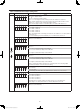
To set, follow steps 1 to 5 below in sequence.
●
This is a required setting.
●
Set the address for the Communication Adaptor control wire.
For the Intelligent Controller internal board, the address is 0. Set a value between 1
and 7 for the external adaptor, ensuring no value is used twice.
Refer to the number (2) “Adaptor number setting procedure” in section
4
“Setting
the Communication Adaptor board”.
* Refer to Table 1 [1].
●
This setting is required for two or more Communication Adaptors.
●
Two links can be connected to a Communication Adaptor.
For links without an air conditioner or other such connection, set the LINK to “off”.
●
The Intelligent Controller can be connected to only four links that are set to be active.
Refer to the number (3) “Setting the inter-unit control wiring connection on/off” in
section
4
“Setting the Communication Adaptor board”.
* Refer to Table 1 [2].
●
This setting is required only for using an Intelligent Controller in conjunction
with a AMY Software.
●
When adding another Communication Adaptor to the inter-unit control wiring,
the adaptor address for the added unit needs to be changed.
* Refer to Table 1 [4] and [5].
●
This setting is not required if pulse input (P1, P2, P3) is not used.
●
Use a pulse meter whose minimum pulse width is normally at least 100 msec.
If and only if a pulse meter 30 msec or higher must be used, use this setting.
* Refer to Table 1 [6].
●
By not using a Interface Adaptor, the confi guration confi rmation time can be
shortened.
●
Not using this setting will not affect operation of the device.
* Refer to Table 1 [7].
(1) Adaptor number setting
(2) Inter-unit control wiring
connection setting
(3) Number of Communication
Adaptor units in one link
setting
(4) Minimum pulse input
detection time setting
(5) Interface Adaptor
connection setting
Complete!
Printed in Japan
Panasonic_CZ-CFUNC1U_Eng.indd 8Panasonic_CZ-CFUNC1U_Eng.indd 8 2011/11/11 12:03:552011/11/11 12:03:55