INSTALLATION INSTRUCTIONS VRF System Air Conditioner This air conditioner uses the refrigerant R410A. NOTE External diameter of service port R410A: 5/16" Model No.
thin aluminum fins on the air conditioner can cut your fingers. IMPORTANT! Please Read Before Starting When Installing… This air conditioning system meets strict safety and operating standards. As the installer or service person, it is an important part of your job to install or service the system so it operates safely and efficiently. Select an installation location which is rigid and strong enough to support or hold the unit, and select a location for easy maintenance.
When Servicing CAUTION • Turn the power OFF at the main power box (mains) before opening the unit to check or repair electrical parts and wiring. • Keep your fingers and clothing away from any moving parts. • Clean up the site after you finish, remembering to check that no metal scraps or bits of wiring have been left inside the unit being serviced. • Do not clean inside the indoor and WARNING outdoor units by users. Engage authorized dealer or specialist for cleaning.
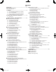
CONTENTS Page IMPORTANT! .................................................................2 Page ■ Ceiling Type (T1 Type) Please Read Before Starting Check of Density Limit 3-40. Required Minimum Space for Installation and Service 3-41. Suspending the Indoor Unit 3-42. Duct for Fresh Air 3-43. Shaping the Tubing 3-44. Installing the Drain Piping 1. GENERAL ...................................................................5 1-1. 1-2. 1-3. 1-4.
1. GENERAL This booklet briefly outlines where and how to install the air conditioning system. Please read over the entire set of instructions for the outdoor unit and make sure all accessory parts listed are with the system before beginning. 1-1. Tools Required for Installation (not supplied) 1-3. Type of Copper Tube and Insulation Material 1. Flathead screwdriver 2. Phillips head screwdriver 3. Knife or wire stripper 4. Tape measure 5. Level gauge 6. Sabre saw or key hole saw 7. Hacksaw 8. Core bits 9.
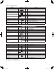
Table 1-1 (4-Way Cassette) Part Name Figure Q’ty Remarks Full-scale installation diagram 1 Printed on container box Drain hose 1 For securing drain hose Hose band 1 For securing drain hose Drain insulator 1 For drain joint 1 For liquid tube 1 For gas tube 2 For gas tube joint Packing 1 For drain joint Wiring cover 1 For covering electrical wiring Screw 4 For full-scale installation diagram Washer 8 For suspending indoor unit from ceiling Screw 1 For fixing the wiring cov
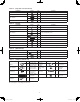
Table 1-4 (High Static Pressure Ducted) Part Name Figure Q’ty Remarks Washer 8 For suspending indoor unit from ceiling Nut 8 For suspending indoor unit from ceiling 1 For gas tube 1 For liquid tube 1 For drain pipe connection Flare insulator Drain socket Table 1-5 (Ceiling) Part Name Figure Q’ty Remarks Full-scale installation diagram 1 Printed on container box Washer 4 For temporarily suspending indoor unit from ceiling Flare insulator T1/8" 2 T3/16" 2 White (heat-resistin
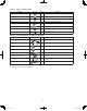
Table 1-8 (Slim Low Static Ducted) Part Name Figure Q’ty Washer Remarks 8 T3 T5 Flare insulation For suspension fitting 2 set For gas / liquid tube connection Insulation tape 2 For gas / liquid tube / flare nut connection Vinyl tie 8 For flare / drain insulating connection 1 For drain tube connection 1 For unit & PVC tube connection Hose band 2 For drain hose connection Short circuit connection 1 For high static pressure (Located on the back of the electrical component box lid.
2. SELECTING THE INSTALLATION SITE Slim Low Static Ducted Type Low Silhouette Ducted (High Static Pressure) Type 4-Way Cassette (60 × 60) Type 2-1. Indoor Unit AVOID: 10 in. ● areas where leakage of flammable gas may be expected. 3 ft. 10 in. ● places where large amounts of oil mist exist. 3 ft. 3 ft. ● direct sunlight. 3 ft. 3 ft. 10 in. ● locations near heat sources which may affect the Fig. 2-1 performance of the unit. ● locations where external air may enter the room directly.
3. HOW TO INSTALL THE INDOOR UNIT Note: For DC Fan Tap Change Procedure for 4-Way Cassette, see page 16. ■ 4-Way Cassette Type (U1 Type) Hole-in-anchor Hole-in-plug 3-1. Preparation for Suspending Concrete Inser t This unit uses a drain pump. Use a level gauge to check that the unit is level. 3-2. Suspending the Indoor Unit (1) Fix the suspension bolts securely in the ceiling using the method shown in the diagrams (Figs.
(2) The length of suspension bolts must be appropriate for a distance between the bottom of the bolt and the bottom of the unit of more than 19/32" as shown in Fig. 3-5. Suspension bolt Suspension lug Nuts and washers (use for upper and lower) (3) Thread the 3 hexagonal nuts and 2 washers (field supply) onto each of the 4 suspension bolts as shown in Fig. 3-5. Use 1 nut and 1 washer for the upper side, and 2 nuts and 1 washer for the lower side, so that the unit will not fall off the suspension lugs.
11-3/16" or less (as short as possible) 33-15/32" or less CAUTION 0 – 45° ● In cases where it is necessary to raise the height of the drain piping, the drain piping can be raised to a maximum height of 33-15/32" above the bottom surface of the ceiling. Under no conditions attempt to raise it higher than 33-15/32" above the bottom surface of the ceiling. Doing so will result in water leakage. (Fig. 3-9) ● Do not install the pipe with an upward gradient from the connection port.
A must be within the range of 15/32" – 43/64" (Fig. 3-13) If not within this range, malfunction or other trouble may occur. 3-6. How to Install the Ceiling Panel 3-6-1. Before Installing the Ceiling Panel Checking the unit position (1) Check that the ceiling hole is within this range: 33-55/64 × 33-55/64 to 35-53/64 × 35-53/64 in. Main unit A (2) Use the full-scale installation diagram (from the packaging) that was supplied with the unit to determine the positioning of the unit on the ceiling surface.
3-6-2. Installing the Ceiling Panel Inter-unit control wiring After completing the wiring process, install the supplied wiring cover before installing the panel. It is not possible to install the wiring cover after installing the panel. The power must be turned ON in order to change the flap angle. (Do not attempt to move the flap by hand. Doing so may damage the flap.
3-6-3. Wiring the Ceiling Panel (Direction that the unit faces has been changed to facilitate explanation.) (1) Open the cover of the electrical component box. Electrical component box cover (2) Connect the 7P wiring connector (red) from the ceiling panel to the connector in the unit electrical component box. (Fig. 3-24) ● If the connectors are not connected, the Auto flap will not operate. Be sure to connect them securely.
3-6-5. Checking After Installation ● Check that there are no gaps between the unit and the ceiling panel, or between the ceiling panel and the ceiling surface. Gaps may cause water leakage and condensation. ● Check that the wiring is securely connected. If it is not securely connected, the auto flap will not operate. (“P09” is displayed on the remote controller.) In addition, water leakage and condensation may occur. 3-6-6.
■ 4-Way Cassette 60 × 60 Type (Y1 Type) Hole-in-anchor Hole-in-plug 3-8. Preparation for Suspending Concrete Insert This unit uses a drain pump. Use a level gauge to check that the unit is level. 3-9. Suspending the Indoor Unit (1) Fix the suspension bolts securely in the ceiling using the method shown in the diagrams, by attaching them to the ceiling support structure, or by any other method that ensures that the unit will be securely and safely suspended. (Fig.
3-11. Installing the Drain Piping (1) Prepare standard hard PVC pipe (O.D. 1-1/32") for the drain and use the supplied hose band to prevent water leaks. (Fig. 3-33) The PVC pipe must be purchased separately. The transparent drain part on the unit allows you to check drainage. Twist tie (4 ties, supplied) Drain hose insulation (supplied) Drain port Hard PVC pipe (equivalent to O.D.
Water drain 3-12. Checking the Drainage After wiring and drain piping are completed, use the following procedure to check that the water will drain smoothly. For this, prepare a bucket and wiping cloth to catch and wipe up spilled water. (1) Connect power to the power terminal board (R, S terminals) inside the electrical component box. (2) Slowly pour approx. 0.13 gal of water into the drain pan to check drainage. (Fig.
3-13-2. Installing the Ceiling Panel The power must be turned ON in order to change the flap angle. (Do not attempt to move the flap by hand. Doing so may damage the flap.) Temporary latches Temporary latch (1) Hang the temporary latches on the inside of the ceiling panel to the receptacle on the unit to temporarily attach the ceiling panel in place. (Fig. 3-44) ● Fig. 3-44 Refrigerant tubing joint Drainage check The ceiling panel must be installed in the correct direction relative to the unit.
3-13-4. How to Attach the Corner & Air-Intake Grille Pin Attaching the corner cover and air-intake grille A. Attaching the corner cover (1) Check that the safety cord from the corner cover is fastened to the ceiling panel pin, as shown in the figure. (Fig. 3-49) Fig. 3-49 (2) Use the supplied screws to attach the corner cover to the ceiling panel. Place the corner cover so that the 3 tabs fit into the holes in the ceiling panel. Then fasten it in place with the supplied screws. B.
-3/64 (2) Depending on the ceiling type: ● Insert suspension bolts as shown in Fig. 3-54 or ● Use existing ceiling supports or construct a suitable support as shown in Fig. 3-55. ● Make sure that the length of suspension bolts from the bottom of the unit is 19/32" or more. (Fig. 3-56) 15-3/4 (Suspension bolt pitch) (1) Follow the diagrams to make the holes in the ceiling. (Figs. 3-52 and 3-53) 3-47/64 23-5/8 19/32 1-27/64 24-13/32 (Outline dimension of panel) 3-14.
3-15. Placing the Unit Inside the Ceiling CAUTION Full-scale installation diagram Be sure to use a level gauge and confirm that the unit is level. If it is not level, water leakage may occur. Suspension lug (1) Use the supplied M5 or 3/16" screws (4) to attach the full-scale installation diagram to the indoor unit suspension lugs, in order to obtain the ceiling opening dimensions for suspending the unit. (Fig.
19/32 CAUTION ● ● The indoor unit includes a drain pump. Be sure to use a level gauge and verify that the unit is level. Before inserting the ceiling material, complete as much of the drain piping work and refrigerant tubing work as possible.
CAUTION ● Do not install an air bleeder as this may cause water to ● ● ● ● ● spray from the drain pipe outlet. (Fig. 3-64) In cases where it is necessary to raise the height of the drain piping, the drain piping can be raised to a maximum height of 33-15/32" above the bottom surface of the ceiling. Under no conditions attempt to raise it higher than 33-15/32" above the bottom surface of the ceiling. Doing so will result in water leakage. (Fig. 3-65) Do not use natural drainage.
3-18. Electrical Power Wiring Drain pipe connection (Be sure to connect the supplied flexible hose.) Refrigerant tubing joint (gas tube) (1) Wiring connections The power inlet is on the side of the indoor unit where the refrigerant tubing is located. The electrical component box is on the lower air intake surface of the indoor unit. (Fig. 3-69) Refrigerant tubing joint (liquid tube) Inter-unit Control Wiring Power supply outlet (2) Wiring WARNING Fig.
Screw Screw de Sli Removing the intake grille Slide the intake grille hooks (2 locations) in the direction of the arrow to open the intake grille. (Fig. 3-72) When the intake grille is open, press a flathead screwdriver against the rear tabs (2 locations) and pull out the intake grille. (Fig. 3-73) Hook Fig. 3-72 Intake grille Removing the side panel Grasp the finger grip on the side panel and slide the panel in the direction of arrow 1 to remove the panel. (Fig.
(5) Align the installation holes on the panel with the bolt holes on the unit. Indoor unit (6) Insert the supplied washer head bolts into the 4 panel installation holes, and tighten until the panel is securely fastened against the unit. (Fig. 3-77) (7) Verify that the panel is securely fastened against the unit. ● At this time, make sure that there is no gap between the indoor unit and the ceiling panel, or between the ceiling panel and the ceiling surface. (Fig.
3-19-3. Wiring the ceiling panel (1) Loosen the 2 screws on the electrical component box lid, and remove the lid. (Fig. 3-80) (2) Fasten the wiring connector (7P, red) which comes out from the ceiling panel using the lead wire clamps (2 locations) on the unit. Then connect it to the connector (7P, red) inside the indoor unit electrical component box. (Fig. 3-81) ● If the connector is not connected, “P09” is displayed on the remote controller, and the automatic flap will not operate.
3-20. Required Minimum Space for Installation and Service Min. 9-27/32 ■ Low Silhouette Ducted Type (F1 Type) A (Suspension bolt pitch) Electrical component box ● This air conditioner is usually installed above the ceiling so that the Table 3-3 Min. 9-27/32 Inspection access 22-27/32 indoor unit and ducts are not visible. Only the air intake and air outlet ports are visible from below. ● The minimum space for installation and service is shown in Fig. 3-84 and Table 3-3.
3-21. Suspending the Indoor Unit Hole-in-anchor Hole-in-plug Concrete Inser t Depending on the ceiling type: • Insert suspension bolts as shown in Fig. 3-86 or • Use existing ceiling supports or construct a suitable support as shown in Fig. 3-87. WARNING It is important that you use extreme care in supporting the indoor unit inside the ceiling. Ensure that the ceiling is strong enough to support the weight of the unit. Before hanging the unit, test the strength of each attached suspension bolt.
3-22. Installing the Drain Piping (1) Prepare standard hard PVC pipe (O.D. 1-1/4") for the drain and use the supplied hose band to prevent water leaks. The PVC pipe must be purchased separately. The transparent drain part on the unit allows you to check drainage. (Fig. 3-91) Align the hose band with end of the hose, and tighten so that it does not contact the bead.
CAUTION Be careful since the fan will start when you short the pin on the indoor control board. Power supply outlet Inter-unit control wiring (4) When the check of drainage is complete, open the check pin (CHK) and remount the insulator and drain cap onto the drain inspection port. 3-24. Increasing the Fan Speed If external static pressure is too great (due to long extension of ducts, for example), the air flow volume may drop too low at each air outlet.
3-25. When Installing the Indoor Unit Confirm that the indoor unit should be installed in a horizontal position. Use the level gauge or vinyl tube and check every four corner of the unit is in horizontal. If the air outlet duct flange is positioned with downward gradient, there is in danger of water splash or drainage. Also, dust may sometimes be contaminated inside the drain pan caused by the residual drain water.
■ Slim Low Static Ducted Type (M1 Type) 32-7/16" (Suspension bolt pitch) min. 7-7/8" 3-27. Required Minimum Space for Installation and Service ceiling so that the indoor unit and ducts are not visible. Only the air intake and air outlet ports are visible from below. ● The minimum space for installation and service is shown in the diagram. ● *H dimension means the minimum height of the unit. ● Select the *H dimension such that a downward slope of at least 1/100 is ensured as indicated in “3-32.
3-28. Preparations Before Installation (Inspection access) 2.3 Arrow view A Inspection access (Field supply) 2.7 (1) Confirm the positional relationship between the unit and suspension bolts. (Refer to the diagram.) • Install the inspection opening on the control box side where maintenance and inspection of the control box are easy. The drain pump can only be inspected through the bottom of the unit. Install the inspection opening also in the lower part of the unit.
3-30. Installing the Duct Connect the duct supplied in the field. Air inlet side ● Attach the duct and intake-side flange (field supply). ● Connect the flange to the main unit with 10 - Ø1/8" (Hole) screws. ● Wrap the intake-side flange and duct connection area with aluminum tape or something similar to prevent air escaping. CAUTION When attaching a duct to the intake-side, be sure to attach an air filter inside the air passage on the intake-side.
3-31. Suspending the Indoor Unit Depending on the ceiling type: • Insert suspension bolts as shown in the diagram or • Use existing ceiling supports or construct a suitable support as shown in the diagram. WARNING Hole-in-anchor Hole-in-plug It is important that you use extreme care in supporting the indoor unit inside the ceiling. Ensure that the ceiling is strong enough to support the weight of the unit. Before hanging the unit, test the strength of each attached suspension bolt.
3-32. Installing the Drain Piping Twist tie (4 ties, supplied) Hard PVC pipe Drain hose insulation (equivalent to Drain port (supplied) O.D. 1-1/32") (Field supply) (1) Prepare standard hard PVC pipe (O.D. 1-1/32") for the drain and use the supplied hose band to prevent water leaks. The PVC pipe must be purchased separately. The transparent drain part on the unit allows you to check drainage. CAUTION Unit: in.
Wiring port Be careful since the fan will start when you short the pin on the indoor control board. CAUTION (4) When the check of drainage is complete, open the check pin (CHK) and remount the insulator and drain cap onto the drain inspection port. Water inlet Eyelet cap 3-34. Increasing the Fan Speed ■ For Short Circuit Connection Fig. 3-117 ● The standard (before shipment) external static pressure is shown in the table below.
■ High Static Pressure Ducted Type (E1 Type) 3-35. Required Minimum Space for Installation and Service 5-1/8 ● This air conditioner is usually installed above the 19-11/16 11-27/64 Min. 23-5/8 (Space for service) 37 ceiling so that the indoor unit and ducts are not visible. Only the air intake and air outlet ports are visible from below. ● The minimum space for installation and service is shown in Fig. 3-118.
3-36. Suspending the Indoor Unit Depending on the ceiling type: ● Insert suspension bolts as shown in Fig. 3-120 or ● Use existing ceiling supports or construct a suitable support as shown in Fig. 3-121. WARNING It is important that you use extreme care in supporting the indoor unit inside the ceiling. Ensure that the ceiling is strong enough to support the weight of the unit. Before hanging the unit, test the strength of each attached suspension bolt.
3-37. Installing the Drain Piping Sealing tape (1) Prepare standard hard PVC pipe (O.D. 1-1/4") for the drain and use the supplied drain socket to prevent water leaks. The PVC pipe must be purchased separately. When doing this, apply adhesive for the PVC pipe at the connection point. Drain pan (2) If connecting a drain joint (supplied) to the threaded drain port, first wrap the drain port threads with sealing tape, then connect the joint. (Fig.
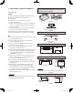
■ Ceiling Type (T1 Type) 3-40. Required Minimum Space for Installation and Service Unit: in. B C Air intake C 12, 18 33-21/32 35-53/64 8-17/64 24 44-19/64 46-29/64 8-17/64 26-49/64 A Type 12-19/32 Dimension B (Suspension bolt pitch) Table 3-6 6-11/16 (1) Dimensions of suspension bolt pitch and unit Ceiling side A 1-5/64 1-5/64 Air outlet (Suspension bolt pitch) Unit: in. Fig.
Figure shows view from top Wall Ceiling 5-45/64 6-7/64 Figure shows view from front * 3-35/64 (4) Wall and ceiling side opening position ø3-15/16 ceiling opening ø3-15/16 wall side opening 3-35/64 ø3-15/16 wall side opening (for left-side drain hose) 5-5/16 ø3-15/16 ceiling opening 4-59/64 * If the optional drain up kit is installed, create a ø3-15/16" hole along the dotted line (part marked with * in figure). Fig. 3-130 3-41.
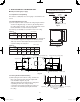
(5) Before suspending the indoor unit, remove the 2 or 3 screws on the latch of the air-intake grilles, open the grilles, and remove them by pushing the claws of the hinges as shown in Fig. 3-135. Then remove both side panels sliding them along the unit toward the front after removing the 2 attachment screws. (Fig. 3-136) Slide toward front side (6) Carry out the preparation for suspending the indoor unit. The suspension method varies depending on whether there is a suspended ceiling or not. (Figs.
3-42. Duct for Fresh Air There is a duct connection port (knock-out hole) at the rightrear of the top panel of the indoor unit for drawing in fresh air. If it is necessary to draw in fresh air, remove the cover by opening the hole and connecting the duct to the indoor unit through the connection port. (Fig.
● Never allow traps to occur in the course of the piping. Twist tie (4 ties) Drain hose Unit drain port insulation (supplied) ● Insulate any piping inside the room to prevent dripping. ● After the drain piping, pour water into the drain pan to check that the water drains smoothly. ● If the drain hose is to be raised, use the optional drain up kit. The drain hose can be raised 23-5/8" above the top of the main unit. (For details, refer to the manual of the optional part.
■ Wall Mounted Type (K1 Type) 3-45. Removing the Rear Panel from the Unit (1) Remove the set screws used to fasten the rear panel to the indoor unit during transportation. (2) Press up on the frame at the 2 locations shown by the arrows in the figure at right, and remove the rear panel. Screws used during transportation Press NOTE Tubing can be extended in 4 directions as shown in Fig. 3-152. Select the direction which will provide the shortest run to the outdoor unit. Left-rear tubing Fig.
3-47. Installing the Rear Panel onto the Wall Confirm that the wall is strong enough to support the unit. See either Item a) or b) below depending on the wall type. a) If the Wall is Wooden (1) Attach the rear panel to the wall with the 10 screws provided. If you are not able to line up the holes in the rear panel with the beam locations marked on the wall, use Rawl plugs or toggle bolts to go through the holes on the panel or drill 3/16" dia.
3-49. Preparing the Tubing Frame (1) Arrangement of tubing by directions a) Right or left tubing The corner of the right or left frame should be cut with a hack saw or similar. (Fig. 3-162) b) Right-rear or left-rear tubing In this case, the corners of the frame do not need to be cut. (2) Be sure to insulate the part of the drain hose that is run indoors, and the refrigerant tubing. If these are not insulated, condensation may result in dripping and damage to walls and furniture.
3-50. Shaping the Tubing Rear panel tab Insulating tape Right-rear tubing (1) Shape the refrigerant tubing so that it can easily go into the hole. (Fig. 3-166) (2) After performing a leak test, wrap both the refrigerant tubing and drain hose together with insulating tape. The drain hose should be positioned below the refrigerant tubes, and should be given sufficient space so that no strong tension is applied to it.
3-52. When Using Wireless Remote Controller Instead of Wired Remote Controller When the wireless remote controller is to be used, slide the switch on the indoor unit control PCB. ● If this setting is not made, an alarm will occur. (The operation lamp on the display blinks.) ● This setting is not necessary if both the wired remote controller and wireless remote controller are used. ● The location of the switch varies depending on the type of PCB used. Check the model name before making the setting.
3-53. External Electronic Expansion Valve Kit (CZ-P56SVK1U) Precautions in this manual are given in the form of “Warnings” or “Cautions.” Both types of precautions contain important information related to your safety, the safety of users, and the correct operation, installation, or maintenance of the air conditioning system. Be sure to carefully observe all relevant precautions. WARNING This symbol refers to a hazard or unsafe practice which can result in severe personal injury or death.
3. Cutting and Flaring of Liquid Tube After determining the position for installation, cut the liquid tube and flare the connecting portion. (Pay attention to the notes below when flaring the tubes.) NOTE ● After cutting the tube, deburr and finish the end face smoothly and correctly. ● Do not damage tubes while flaring. ● Take care not to allow dirt and deburred chips into the tube. ● Use the flare nut which came with External Electronic Expansion Valve Kit.
5. Flare Insulation of Tubing After completing a leakage test, apply heat insulation. (Fig. 3-191) * Use the flare insulator provided with the product. Indoor side Outdoor side Insulating tape Flare insulator Insulating tape Clamps (small) Clamps (small) Flare insulator Be careful not to allow a gap to occur between the thermal insulation of the tubing and the thermal insulation of the main unit. Fig. 3-173 6.
7. Wiring Procedure WARNING Be sure to turn the power off at the mains before removing or connecting connectors to avoid electric shock hazard. Connection of External Electronic Expansion Valve with Extension Cord (1) Turn the power off. (2) Turn the power on. (3) Wait 1 minute after the power is on and then turn the power off again at the mains. * The electronic expansion valve becomes full-open in the 1 minute. Do not give instructions for operation through the remote controller during this time.
■ Floor Standing Type (P1 Type) Concealed Floor Standing Type (R1 Type) Horizontal view 3-54. Required Minimum Space for Installation and Service min. 3-15/16" Vertical view min. 3-15/16" min. 3.3 ft. Install the unit where cooled or heated air from the unit can circulate well in the room. Do not put obstacles which may obstruct the air flow in front of the air intake and outlet grilles. min. 3.3 ft. NOTE Fig.
Concealed Floor Standing Type (R1 Type) 4-Ø15/32" holes (for fastening the indoor unit to the floor with screws) Air filter Refrigerant connection outlet (liquid tube) Refrigerant connection outlet (gas tube) Level adjusting bolt Drain outlet (20 A) Flange for air-outlet duct Unit: in.
3-56. Removing and Attaching the Front Panel (Floor Standing Type) A NOTE A dew-prevention heater is secured behind the front panel. When removing or attaching the panel, take care not to damage the lead wire to the heater. Tab How to remove the front panel Side panel (1) Remove the 2 screws at the lower part of the front panel. Front panel B Fig. 3-180 (2) Holding A at the upper right of the unit, push up at B at the lower right of the panel. The right side of the front panel is removed.
CAUTION Insulate both gas and liquid tubes. Insulating tape (black) Flare insulator Insulating tape (white) ● To insulate tubes (1) Wrap the flare nuts with the supplied white insulating tape. (2) Wrap the flare nuts with the supplied flare insulator. (3) Fill the clearance between the union insulator and flare insulator with black insulating tape. Fasten both ends of the flare insulator with the supplied vinyl clamps. Flare nut Insulator Vinyl clamps Fig. 3-183 3-58.
■ SUPPLEMENT ON DRAIN PIPING 1. Drain hose installation Drain port (Drainage check section on drain port, transparent, ABS resin) Hose band (supplied) Soft PVC socket Hard PVC socket (VP25) Hard PVC pipe (VP25 field supplied) Drain hose (supplied) Indoor unit Bead Adhere with PVC adhesive. Do not use adhesive here. * Drain port may possibly be damaged if PVC adhesive is used. * Apply approx. 0.07 oz of the adhesive on both sides of the supplied drain hose with a joint socket and hard PVC pipe.
4. ELECTRICAL WIRING 4-1. General Precautions on Wiring (1) Before wiring, confirm the rated voltage of the unit as shown on its nameplate, then carry out the wiring closely following the wiring diagram. (2) Provide a power outlet to be used exclusively for each unit, and a power supply disconnect, circuit breaker and earth leakage breaker for overcurrent protection should be provided in the exclusive line. (3) To prevent possible hazards from insulation failure, the unit must be grounded.
4-3. Wiring System Diagram ex.) W-3WAY ECO-i Power supply 208 / 230V, 60Hz, 1-PH Remote Controller WHT 1 BLK 2 L1 L2 Indoor unit (No. 1) * Outdoor unit INV unit L1 L2 Ground B 1 2 * A U1 1 U2 2 R1 3 R2 4 L1 L2 L3 L1 L2 L3 Power supply 208 / 230V, 60Hz, 3-PH Ground A Power supply 208 / 230V, 60Hz, 1-PH L1 L2 Indoor unit (No.
CAUTION (1) When linking outdoor units in a network, disconnect the terminal extended from the short plug (CN003, 2P Black, location: right bottom on the outdoor main control PCB) from all outdoor units except any one of the outdoor units. (When shipping: In shorted condition.) For a system without link (no connection wiring between outdoor units), do not remove the short plug. (2) Do not install the inter-unit control wiring in a way that forms a loop. (Fig.
Loose wiring may cause the terminal to overheat or result CAUTION in unit malfunction. A fire hazard may also exist. Therefore, ensure that all wiring is tightly connected. When connecting each power wire to the terminal, follow the instructions on “How to connect wiring to the terminal” and fasten the wire securely with the fixing screw of the terminal plate.
4-4. Important Note When Wiring for Common Type Connect the wires referring to the diagram. Note that the control wirings (Low voltages) shall be segregated from the power supply wires (High voltage) as follows: 1. Connect the Inter-unit control wiring to U1/U2 terminals and the remote control wire to R1/R2. (excepting K1 type). 2. Connect the power supply wires to “L1, L2” of the terminal block. Be sure to connect the grounding conductor of the incoming power supply to the earth (ground) screw. 3.
Important Note When Wiring for Common Type (Continued) T1 Type E1 Type Remote control wiring and Inter-unit control wiring (field supplied) Clamping clip Remote control wiring (field supplied) Clamping clip Conduit (field supplied) Earth screw Earth screw Power wiring (field supplied) Power wiring (field supplied) Conduit (field supplied) P1, R1 Type M1 Type Clamping clip Power wiring (field supplied) Connection for Solenoid Valve Kit (for 3WAY) Earth screw Power wiring (field supplied) Eart
Important Note When Wiring for Common Type (Continued) K1 Type Model : S-07MK1U6 S-09MK1U6 S-12MK1U6 Clamping strap Connection for Solenoid Valve Kit (for 3WAY) Power wiring (field supplied) Remote control wiring and Inter-unit control wiring (field supplied) Conduit (field supplied) K1 Type Connection for Solenoid Valve Kit (for 3WAY) Clamping strap Model : S-18MK1U6 S-19MS1U6* S-12MK1U6 Power wiring (field supplied) Earth screw Remote control wiring and Inter-unit control wiring (field supplie
4-5. Important Note When Wiring for Y1 Type Connect the wires referring to the diagram. Note that the control wirings (Low Voltages) shall be segregated from the power supply wires (High Voltage) as follows: 1. Connect the Inter-unit control wiring to U1/U2 terminals and the remote control wire to R1/R2. Then place and fix the two clasps so that the clasps shall cover both the remote control wires, the Interunit control wiring and the 3-way wiring harness as shown in the magnified drawing. 2.
5. HOW TO PROCESS TUBING Deburring The liquid tubing side is connected by a flare nut, and the gas tubing side is connected by brazing. Before After 5-1. Connecting the Refrigerant Tubing Use of the Flaring Method Many of conventional split system air conditioners employ the flaring method to connect refrigerant tubes which run between indoor and outdoor units. In this method, the copper tubes are flared at each end and connected with flare nuts.
Caution Before Connecting Tubes Tightly (1) Apply a sealing cap or water-proof tape to prevent dust or water from entering the tubes before they are used. (2) Be sure to apply refrigerant lubricant to the matching surfaces of the flare and union before connecting them together. This is effective for reducing gas leaks. (Fig. 5-4) (3) For proper connection, align the union tube and flare tube straight with each other, then screw in the flare nut lightly at first to obtain a smooth match. (Fig.
5-3. Insulating the Refrigerant Tubing Tubing Insulation ● Thermal insulation must be applied to all unit tubing, including the distribution joint (purchased separately). (Fig. 5-7) * For gas tubing, the insulation material must be heat resistant to 248°F or above. For other tubing, it must be heat resistant to 176°F or above. Two tubes arranged together Gas tubing Liquid tubing Insulation Three tubes arranged together Cosmetic (finishing) tape Insulation material thickness must be 25/64 in.
5-4. Taping the Tubes (1) At this time, the refrigerant tubes (and electrical wiring if local codes permit) should be taped together with armoring tape in 1 bundle. To prevent the condensation from overflowing the drain pan, keep the drain hose separate from the refrigerant tubing. (2) Wrap the armoring tape from the bottom of the outdoor unit to the top of the tubing where it enters the wall. As you wrap the tubing, overlap half of each previous tape turn.
6.
■ Care and Cleaning WARNING Air intake and outlet side (Indoor unit) 1. For safety, be sure to turn the air conditioner off and also to disconnect the power before cleaning. 2. Do not pour water on the indoor unit to clean it. This will damage the internal components and cause an electric shock hazard. Clean the air intake and outlet side of the indoor unit with a vacuum cleaner brush, or wipe them with a clean, soft cloth.
■ Care and Cleaning (continued) How to remove the filter 4-Way Cassette (U1): 4-way Cassette 60 × 60 (Y1): 1. Use a screwdriver to remove the bolt screw on each side for the two latches. (Be sure to reattach the two bolt screws after cleaning.) 2. Press on the two latches of the air intake grille with your thumbs in the direction of the arrow to open the grille. 3. Open the air intake grille downward. ● When cleaning the air filter, never remove the safety chain.
■ Care and Cleaning (continued) How to remove the filter (continued) Ceiling (T1): 1. Take hold of the finger-hold on the air intake grille and press it to the rear, and the grille will open downward. 2. Take hold of the finger-hold on the air filter, pull it toward you. Air filter finger-hold Air intake grill Air intake grill finger-hold de Hook Sli Screw Air filter Screw Latch Air filter finger-hold *Take hold of the finger-hold on the air filter, pull it toward you. Wall Mounted (K1): 1.
■ Care and Cleaning (continued) How to remove the filter (continued) Floor Standing (P1): Concealed Floor Standing (R1): 1. Remove the screw at the bottom left of the front panel using a Phillips head screwdriver. (Be sure to replace the screw when cleaning is finished.) 2. Remove the filter by pulling it toward you. Screw Cleaning the drain filter and drain pan Floor standing (P1): Air filter Air filter Screw 1.
CAUTION 1. Certain metal edges and the condenser fins are sharp and may cause injury if handled improperly; special care should be taken when you clean these parts. 2. Periodically check the outdoor unit to see if the air outlet or air intake is clogged with dirt or soot. 3. The internal coil and other components of the outdoor unit must also be cleaned periodically. Consult your dealer or service center.
■ Troubleshooting If your air conditioner does not work properly, first check the following points before requesting service. If it still does not work properly, contact your dealer or a service center. Trouble Possible Cause Air conditioner does not run at 1. Power failure. all. 2. Leakage circuit breaker has tripped. 3. Line voltage is too low. 4. Operation button is turned off. 5. The wireless remote controller or heat pump is malfunctioning. 6. Batteries in wireless remote controller have run down.
VRF_Indoor_US.
VRF_Indoor_US.
DC0811-10911 Printed in Japan VRF_Indoor_US.