
Installation Manual

43
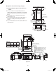
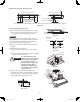
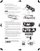
Sealing tape
Drain joint
(supplied)
Drain pan
Drain opening
(25A or 1-11/32
" male screw)
Fig. 3-123
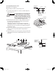
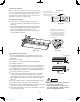
Good
Min. 1/100
Downward gradient
Not good
Fig. 3-124
Min. 1-31/32 in.
Inspection plug
Min.
3-15/16 in.
Fig. 3-125
3-37. Installing the Drain Piping
(1) Prepare standard hard PVC pipe (O.D. 1-1/4") for the
drain and use the supplied drain socket to prevent water
leaks. The PVC pipe must be purchased separately.
When doing this, apply adhesive for the PVC pipe at the
connection point.
(2) If connecting a drain joint (supplied) to the threaded
drain port, fi rst wrap the drain port threads with sealing
tape, then connect the joint. (Fig. 3-123)
(3) After connecting the drain pipe securely, wrap insulator
(fi eld supply) around the pipe.
(4) Ensure the drain pipe has a downward gradient (1/100
or more) and prepare traps as indicated in Fig. 3-124.
(5) Also, in another part of the pipe arrangement, prepare
traps with an inspection plug to clean dust or debris that
may cause leaking of water. (Fig. 3-125)
(6) After connecting the drain piping, slowly pour water into
the drain pan to check that the water drains smoothly.
3-38. Caution for Ducting Work
This unit has high static pressure (applicable external
●
static pressure Max. 0.68 – 0.88 in. WG. In the case of
small pressure resistance (for instance, a short duct),
install a damper for adjusting air fl ow volume as air fl ow
volume / air fl ow noise increases.
If the air conditioner is to be installed in a room such as
●
an offi ce or meeting room which needs a low sound level,
provide a supply and return noise absorption chamber
with an acoustic liner.
Include an air fi lter (fi eld supply) at the return duct.
●
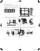
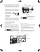
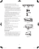
Limit line
Limit line
H
H
M
M
L
883 1059 1236
Air Flow (CFM) Air Flow (CFM)
External Static Pressure
0
0.40
0.20
0.60
0.80
1.00
(in. WG)
External Static Pressure
0
0.40
0.20
0.60
0.80
1.00
(in. WG)
Limit line
Limit line
H
H,M
M
L
1059 1236 1412
36 Type 48 Type
H: At shipment
NOTE
Fig. 3-126
3-39. Indoor Fan Performance
How to Read the Diagram
The vertical axis is the External Static Pressure
(in. WG) while the horizontal axis represents the
Air Flow (CFM). The characteristic curve for the
“H,” “Med,” and “Lo” fan speed control.
The nameplate values are shown based on the
“H” air fl ow. Therefore in the case of 36 Type,
the fl ow is 1059 CFM, while the External Static
Pressure is 0.72 in. WG at “H” position. If the
external static pressure is too great (due to long
extension of duct, for example), the air fl ow
volume may drop too low at each air outlet. (Fig.
3-126)
VRF_Indoor_US.indb 43VRF_Indoor_US.indb 43 2011/09/30 12:23:092011/09/30 12:23:09