
Installation Manual

6
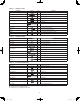
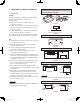
Table 1-1 (4-Way Cassette)
Part Name Figure Q’ty Remarks
Full-scale installation diagram 1 Printed on container box
Drain hose
1 For securing drain hose
Hose band 1 For securing drain hose
Drain insulator
1 For drain joint
Flare insulator
1 For liquid tube
1 For gas tube
Insulating tape
White
(heat-resisting)
2 For gas tube joint
Packing
1 For drain joint
Wiring cover
1 For covering electrical wiring
Screw
4 For full-scale installation diagram
Washer
8 For suspending indoor unit from ceiling
Screw
1 For fi xing the wiring cover
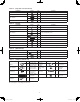
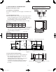
Table 1-2 (1-Way Cassette)
Part Name Figure Q’ty Remarks
Full-scale installation diagram
1 Printed on container box
Drain hose
1 For securing drain hose
Hose band
1 For securing drain hose
Drain insulator 1 For drain joint
Flare insulator
1 For liquid tube
1 For gas tube
Insulating tape
White
(heat-resisting)
2 For gas tube joint
Packing 1 For drain joint
Washer 8 For suspending indoor unit from ceiling
Screw
4 For full-scale installation diagram
Bushing 1 For electrical junction box
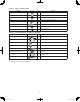
Table 1-3 (Low Silhouette Ducted)
Part Name Figure Q’ty Remarks
Drain hose
1 For securing drain hose
Hose band
1 For securing drain hose
Packing 1 For drain joint
Drain insulator 1 For drain joint
Flare insulator
1 For liquid tube
Insulating tape
White
(heat-resisting)
2 For gas and liquid tubes fl are nuts
Flare insulator
1 For gas tube
Washer
8 For suspending indoor unit from ceiling
Sealing putty
1 For sealing recessed portion of power supply
Vinyl clamp 8 For fl are and drain insulators
Use M10 or 3/8" for suspending bolts. ●
Field supply for suspending bolts and nuts. ●
VRF_Indoor_US.indb 6VRF_Indoor_US.indb 6 2011/09/30 12:22:542011/09/30 12:22:54