Operating Instructions Installation Instructions provided HD Integrated Camera Model No. AW‑HE50HN AW‑HE50SN Before operating this product, please read the instructions carefully and save this manual for future use. For instructions on how to operate this HD Integrated Camera and how to establish its settings, refer to the “Operations and Settings” manual (PDF file) which can be found on the CD-ROM supplied with the camera.
Safety precautions WARNING: CAUTION TO PREVENT INJURY, THIS APPARATUS MUST BE SECURELY ATTACHED TO THE FLOOR/WALL IN ACCORDANCE WITH THE INSTALLATION INSTRUCTIONS. RISK OF ELECTRIC SHOCK DO NOT OPEN CAUTION: TO REDUCE THE RISK OF ELECTRIC SHOCK, DO NOT REMOVE COVER (OR BACK). NO USER SERVICEABLE PARTS INSIDE. REFER TO SERVICING TO QUALIFIED SERVICE PERSONNEL.
Safety precautions IMPORTANT SAFETY INSTRUCTIONS Read these operating instructions carefully before using the unit. Follow the safety instructions on the unit and the applicable safety instructions listed below. Keep these operating instructions handy for future reference. 10) Protect the power cord form being walked on or pinched particularly at plugs, convenience receptacles, and the point where they exit from the apparatus. 1) Read these instructions. 2) Keep these instructions. 3) Heed all warnings.
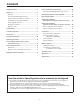
Contents Safety precautions ............................................................ 2 How to install and connect the unit ............................... 20 Before use .......................................................................... 5 When using the WV‑Q105 (optional accessory) ........... 24 Overview ......................................................................... 5 Changing the direction of the nameplate . .................... 25 Concerning the Operating Instructions ........
Before use wwConcerning the Operating Instructions wwOverview pp This unit is a compact full HD camera integrated with a pan-tilt head and featuring a newly developed 1/3-inch full HD MOS sensor and digital signal processor (DSP). pp For the purposes of this manual, the model number AW‑HE50HN is referred to as the “AW‑HE50H”, the AW‑HE50SN as the “AW‑HE50S” and model numbers AW‑HE50HN and AW‑HE50SN will be referred to together as the “AW‑HE50”.
Before use wwRequired personal computer environment CPU Intel® CoreTM2 DUO 2.4 GHz or faster recommended Memory 512 MB or more (When using Microsoft® Windows Vista®: 1 GB or more, and when using Microsoft® Windows® 7: 1 GB [32 bits] or 2 GB [64 bits] or more) IMPORTANT pp Failure to provide the required personal computer environment may slow down the delineation of the images on the screen, make it impossible for the web browser to work and cause other kinds of problems.
Before use wwDisclaimer of warranty wwNetwork security IN NO EVENT SHALL Panasonic System Networks Co., Ltd. BE LIABLE TO ANY PARTY OR ANY PERSON, EXCEPT FOR REPLACEMENT OR REASONABLE MAINTENANCE OF THE PRODUCT, FOR THE CASES, INCLUDING BUT NOT LIMITED TO BELOW: As you will use this unit connected to a network, your attention is called to the following security risks.
Characteristics Integrated pan-tilt head unit, camera and lens to facilitate installation pp By designing the camera, lens and pan-tilt head as a single integrated unit, the time taken for the installation work has been drastically reduced. Multiple number of formats supported pp Switching between the 1080/59.94i, 720/59.94p and 480/59.94i formats can be accomplished using a menu. By using VIDEO OUT signals, HD format signals and SD format signals can be output at the same time.
Controller supported pp AW‑RP655 pp AW‑RP555 pp AW‑RP50 Notes When connecting the AW‑RP655 pp The camera menus that are operated using the LCD panel on the AW‑RP655 cannot be used. Use the camera menus displayed on the monitor which has been connected to the unit. It may be necessary to upgrade the version of the controller in order to support the unit. Consult with your dealer. When connecting the AW‑RP555 pp The AW‑RP555 periodically transmits the POWER‑ON command to the pan-tilt head.
Installation precautions In addition to heeding the points presented in the “Safety precautions”, observe the following precautions as well. Concerning the installation location Install the unit in a stable location which will not be susceptible to shaking. If the unit is installed in a location which is susceptible to shaking, this will cause the unit’s images to shake in turn. Install the unit after conferring in detail with your dealer.
Installation precautions Connecting the power cable Be absolutely sure to connect the power cable of the AC adapter through a circuit breaker using one of the following methods. (1) Connect the power cable through a power control unit. (2) Connect the power cable to a circuit breaker in a power distribution panel with a contact distance of 3.0 mm or more. Use a circuit breaker which is capable of shutting off all the poles of the main power supply with the exception of the protective ground conductor.
Operating precautions Zooming and focusing When the focus is set manually, out-of-focusing may occur during zooming. After zooming, if necessary, either adjust the focus or set the focus to auto. When using the focus at the manual setting, proceed with zooming after setting the focus position at the Tele end where the focusing accuracy is higher. (However, if the distance from the unit to the subject is less than 1.5 meters [4.92 ft.], the subject may shift out of focus at the Wide end.
Operating precautions Turn off the power before connecting or disconnecting the cables. Always be sure to turn off the power before connecting or disconnecting the cables. Maintenance Turn off the unit’s power before proceeding with maintenance. Otherwise, you may injure yourself. Wipe the surfaces using a soft dry cloth. Avoid all contact with benzene, paint thinners and other volatile substances, and avoid using these substances. Otherwise, the casing may become discolored. Handle the unit carefully.
Concerning the wireless remote control (optional accessory) This unit can be operated by remote control using a wireless remote control (model number: AW‑RM50G) purchased separately. Check out the following points before using the wireless remote control. Consult your dealer concerning the purchase of a wireless remote control. pp Operate the wireless remote control from positions less than 10 meters (32.8 ft.) away from the unit.
Parts and their functions wwCamera unit 1 Mount bracket for installation surface (supplied accessory) Mount this bracket onto the installation surface, and then attach the camera main unit to the bracket. 2 Drop-prevention wire Pull out the wire from the bottom panel of the camera main unit, and attach it to the hook of the mount bracket. 3 Hole for securing the camera pedestal This hole is provided in the bottom panel of the camera pedestal.
Parts and their functions IR ID switches [IRID] 9 LAN connector for IP control [LAN ACT/LINK] This LAN connector (RJ45) is connected when exercising IP control over the unit from an external device. Use a cable with the following specifications for the connection to the LAN connector: [CAM1] When connecting through a hub: LAN cable* (category 5 or above, straight cable), max. 100 meters [328 feet] When a hub is not used: LAN cable* (category 5 or above, crossover cable), max.
Parts and their functions 3 MENU button wwWireless remote control (optional accessory) Each time this is pressed for 2 seconds, operation switches between displaying the unit’s menu and exiting the menu. When it is pressed quickly (for less than 2 seconds) while a menu is displayed, the setting change is canceled. Furthermore, the pan and tilt movement range limits (limiters) are set and released by operating the MENU button, PRESET/LIMIT button and the pan‑tilt buttons ([], [], [] and []).
Parts and their functions A/FOCUS button 9 PRESET/LIMIT button This is used when automatically adjusting the lens focus. This is used to register the settings in the preset memories or set or release the limiters. When a preset memory call button is pressed while the PRESET/LIMIT button is held down, the information on the unit’s current direction and other settings is registered in the call button. Preset memory call buttons [1] to [12] correspond to the unit’s No.1 to No.12 preset memories.
Setting the remote control IDs The wireless remote control (optional accessory) is capable of operating up to four units. IDs are used to set which units are selected when the [CAM1], [CAM2], [CAM3] and [CAM4] buttons on the wireless remote control have been pressed. pp When using a multiple number of units, set a different remote control ID for each unit. pp When using one unit, set the remote control ID to “CAM1” unless the setting needs to be changed.
How to install and connect the unit Be absolutely sure to read through the “Installation precautions” on pages 10 to 11. The procedure given here is for the kind of installation where the unit is suspended from an overhead surface, but the same steps are followed for a stand-alone installation. If the ceiling panel is not strong enough to bear the unit’s weight, use the kind of mount bracket that is supported by anchor bolts between the concrete ceiling and ceiling panel.
How to install and connect the unit 2 Mount the mount bracket onto the installation surface. pp Use the bracket mounting screws (M4, bind-head: 10 mm long) supplied with the unit. pp For proper clamping torque, securely attach the screws using the specified tools. Screw diameter Clamping torque M4 1.47 N · m (15 kgf · cm) Bracket mounting screws 4 (supplied) (M4, bind-head) Note pp Use only the screws supplied with the unit. Do not use any other screws such as wood screws, nails, etc.
How to install and connect the unit 4 Mount the unit. pp Align the position of the hole for checking the positioning with the status display lamp. pp Align the holes on the camera main unit used to insert the bottom panel with the protrusions on the mount bracket used for inserting the camera, push the bracket and camera firmly together, and rotate the main unit by about 15 degrees in the direction of the arrow. pp Secure the mount bracket to the unit using the main unit mounting screws (M3) as supplied.
How to install and connect the unit 6 Connect the rear panel connectors. Anchor the AC adapter cable in place using the cable clamp.
How to install and connect the unit wwWhen using the WV‑Q105 (optional accessory) It is recommended that you provide an inspection opening or other such space for access purposes in the area near where the equipment is installed in order to facilitate installation and the wiring connections work. Before mounting the mount bracket, check that the installation location is strong enough to withstand the total mass (approx. 2.0 kg [4.41 lbs.]) which will be exerted once the camera is mounted.
Changing the direction of the nameplate When the unit is mounted on the ceiling, its nameplate will be upside down. The direction of the unit’s nameplate can be changed. 1 Push in the part indicated by the arrow, and pull out the nameplate. 2 Change the direction of the nameplate. 3 Push the nameplate back into place.
Removing the camera 1 2 Turn off the circuit breaker and power. Remove the cable cover. pp Remove the screw (M3) for the cable cover used to secure the cover. pp Push the tab parts of the cover to disengage the cover. 3 Disconnect the cables. Disconnect the power cable, video cable, and control cable, etc. 4 5 Remove the main unit mounting screw used to secure the unit and mount bracket. Push the unit (1). Turn it approximately 15 degrees away from the installed position (2), and remove it (3). Approx.
Stand-alone installation (when the mount bracket is going to be used) The same steps are followed as for the kind of installation where the unit is suspended from an overhead surface (pages 20 to 23). 1 Check the mounting space. Note pp As with installing the unit suspended from an overhead surface, carefully check the space where the unit will be mounted, and then decide if it is appropriate to install the unit in that space. 2 Mount the mount bracket onto the installation surface.
Stand-alone installation (when the mount bracket is going to be used) 5 Check the mounting. 6 Connect the rear panel connectors.
Stand-alone installation (when the mount bracket is not going to be used) wwWhen installing the unit on a desktop Place the unit flat on the surface. Notes pp Install the unit in a stable location which will not be susceptible to shaking. If the unit is installed in a location which is susceptible to shaking, this will cause the unit’s images to shake in turn. pp Take care not to allow the unit to fall or otherwise be damaged during installation. pp When carrying the unit, do not hold it by its head.
Connections wwConnections with an HD monitor HD Integrated Camera AW‑HE50 HDMI signal (AW‑HE50H only), SDI signal (AW‑HE50S only) or HD analog component signal HD monitor Wireless remote control (optional accessory) Up to four units can be operated using one remote control.
Connections wwConnections with a controller (AW‑RP655 or AW‑RP555) LAN cable (straight cable) Pan-tilt head/ camera control signals HD Integrated Camera AW‑HE50 Multi Hybrid Control Panel AW‑RP555 HDMI/SDI video signal AC Adapter AW‑PS510A Monitor OUT IN V PR RJ-45 relay adapter Multi-Function Controller AW‑RP655 AC Adapter AW‑PS510A 31 PB Y Multi-Interface Cable AW‑CA20T6 Accessory AC adapter
Connections wwSystem example 1 HD Integrated Camera AW‑HE50S HD Integrated Camera* AW‑HE50S Accessory AC adapter Genlock signal generator Pan-tilt head and camera control signal SDI video signal Monitor 1 Monitor 2 Monitor Monitor Switcher System TALLY Multi-Function Controller AW‑RP655 AC Adapter AW‑PS510A *: The AC adapter provided with the unit is not shown in the above figure. pp SDI output is supported only by the AW‑HE50S.
Connections wwSystem example 2 HD Integrated Camera AW‑HE50S HD Integrated Camera* AW‑HE50S Accessory AC adapter Genlock signal generator LAN cable (straight cable) SDI video signal Monitor 2 Switching hub Monitor 1 LAN cable (straight cable) Monitor Monitor Compact Live Switcher AW‑HS50 Remote Camera Controller AW‑RP50 *: The AC adapter provided with the unit is not shown in the above figure. pp SDI output is supported only by the AW‑HE50S.
Network settings wwUse the Easy IP Setup Software to establish the unit’s settings wwInstalling the software Be absolutely sure to read through the “Readme.txt” on the CD-ROM supplied with the unit first before attempting to install the software. The settings related to the unit’s network can be established using the Easy IP Setup Software supplied. To establish the settings for a multiple number of units, the settings must be selected for each camera involved.
Network settings 1 2 Start the Easy IP Setup Software. Click the MAC address/IP address of the camera to be set, and click the [IP setting] button. pp After the [Apply] button is clicked, it takes about 2 minutes for the settings in the unit to be completed. If the AC adapter or LAN cable is disconnected before the settings are completed, the settings will be canceled. In this case, repeat the steps to establish the settings.
Troubleshooting qqOperation Symptom No power Cause and remedial action pp Is the AC adapter securely connected to the AC outlet? ––– pp If the power plug of the AC adapter connected properly? ––– pp If the unit is connected to the controller, has it been connected properly? Refer to the Operating Instructions of the controller. pp When the unit is being operated by the wireless remote control A lso refer to the “Cannot operate using the wireless remote control” item.
Troubleshooting Symptom The adjustment of the slowest speed at which the camera is to start panning and tilting fails to be completed for the AW‑RP655 or AW‑RP555 The web setting screen cannot be accessed Cause and remedial action Reference pages Do not attempt to adjust the slowest speed at which the camera is to start panning and tilting since this adjustment does not need to be undertaken when the unit is connected with the AW‑HE50.
Troubleshooting Symptom The web setting screen cannot be accessed Cause and remedial action Reference pages pp Has the same IP address setting been used for another device? Is there a lack of consistency between the address set and the network subnet at the installation destination? [ When the personal computer is connected to the unit within the same subnet] Have the IP addresses of the unit and personal computer been set to the subnet shared by the unit and computer? Has the “Use proxy server” sett
Troubleshooting qqVideo Symptom Cause and remedial action pp Has the unit been connected properly to the other connected devices? Reference pages P.30 to 33 pp If the system is configured in such a way that the picture is also switched when the unit to be operated is selected, has the correct unit been selected? P.9 pp Has the video signal setting been selected correctly? P.43, P.
Troubleshooting Symptom Ring-shaped reflections appear in the four corners of the images Something is wrong with the coloring of the pictures The pictures are too light or too dark Cause and remedial action Reference pages pp These are caused by the reflections of the light between the lens and the cover in front of the lens. Find a way of optimizing the position of the lighting relative to the position of the unit, and install and use the unit in a location where the reflections will not occur.
Troubleshooting qqWeb settings Depending on the OS installed on the PC, the following may occur. Follow the instructions below when the following has occurred. By performing the following solutions, other applications and the security level may not be affected. The “Information bar” expressed in the following symptom and solutions will be displayed just below the address bar only when there is information to communicate.
Appearance Unit: mm (inch) R (R 80 35/3 2 160 (6-5/16) 85 (3-11/32) 123 (4-13/16) 3 (1/8) 55 (2-3/16) 175 (6-7/8) ) AW‑HE50H 80 (3-5/32) 72 (2-13/16) 166 (6-9/16) AW‑HE50S 42
Specifications Power requirements: DC 12 V 10 % (AC adapter provided) Power consumption: DC 12 V, 1.2 A (AW‑HE50H) DC 12 V, 1.3 A (AW‑HE50S) indicates safety information. ww GENERAL ww INPUT Ambient operating temperature: 0 °C to +40 °C (32 °F to +104 °F) Input connector: DC 12 V IN, EXT SYNC IN (BNC) (AW‑HE50S only) BBS (Black Burst Sync) signal supported Storage temperature: –20 °C to +50 °C (–4 °F to +122 °F) Allowable humidity ranges: 20 % to 90 % (no condensation) Mass: Approx. 1.
Specifications ww FUNCTIONS AND PERFORMANCE Camera/pan-tilt head control: IP connecting cable [Camera unit] Imaging sensors: 1/3˝ Full-HD MOS Lens: Motorized 18 zoom, f/1.6 to 2.8 (f=4.7 to 84.6 mm; 35 mm equivalent: 36.9 mm to 664.5 mm) Focus: RP connecting cable Switching between auto and manual Focus distance: Entire zooming range: 1.5 m (4.9 ft.) Wide end: 30 cm (0.98 ft.) Color separation optical system: On-chip color filter system Protocol Minimum illumination: 3 lx (50 IRE, F1.
Memo
Panasonic Solutions Company 3 Panasonic Way, Secaucus, NJ 07094 Tel: 877-803-8492 www.panasonic.com/broadcast e-mail: MediaProServices.PSC@us.panasonic.com Panasonic Canada Inc. 5770 Ambler Drive, Mississauga, Ontario L4W 2T3 Tel: 905-624-5010 Panasonic de México S.A. De C.V. Casa Matriz: Felix Cuevas No. 6 Pisos 2 y 3 Col. Tlacoquemecatl Del Valle Del.Benito Juárez México, D.F., C.P.03200 Tel: 55-5488-1000 Fax: 55-5575-6763 Panasonic Latin America, S.A. P.O.
Operating Instructions HD Integrated Camera Model No.
Contents Before use .......................................................................... 3 Setting the menu items ................................................... 38 Overview ......................................................................... 3 Setting the menu items ................................................. 38 Concerning the Operating Instructions ........................... 3 Top Menu ......................................................................
Before use wwConcerning the Operating Instructions wwOverview pp This unit is a compact full HD camera integrated with a pan-tilt head and featuring a newly developed 1/3-inch full HD MOS sensor and digital signal processor (DSP). pp For the purposes of this manual, the model number AW‑HE50HN is referred to as the “AW‑HE50H”, the AW‑HE50SN as the “AW‑HE50S” and model numbers AW-HE50HN and AW-HE50SN will be referred to together as the “AW-HE50”.
Before use wwRequired personal computer environment CPU Intel® CoreTM2 DUO 2.4 GHz or faster recommended Memory 512 MB or more (1 GB or more when using Microsoft® Windows Vista®) pp When using Microsoft® Windows Vista® or Microsoft® Windows® 7, refer to the “Notes on Windows Vista®/ Windows® 7” (page 84) for details on the personal computer environment that is required and on the precautions and other items.
Before use wwDisclaimer wwNetwork-related precautions Panasonic Corporation will accept absolutely no responsibility whatsoever when any of the following is applicable: This unit is connected to a network and used: As such, it may be susceptible to the following damage, harm or losses.
Basic shooting operations 1 2 3 Set the subject brightness to the appropriate level. With the basic operations, it is assumed that the focus, iris and white balance will be adjusted automatically (as per the factory settings). If the settings have already been changed and the original settings are to be restored, refer to the “What to do when encountering problems in the basic shooting operations” (page 13) and “Camera screen” (page 39) in “Setting the menu items”.
How to turn the power on and off wwTurning the power on When performing the operations using the controller When performing the operations using the wireless remote control When the AW‑RP655 or AW‑RP555 is connected: 1 Set all the power switches of the units and devices connected in the system to ON. 1 pp This unit does not have a power switch. When power is supplied to it, the status display lamp will light up orange.
How to turn the power on and off wwTurning the power off When performing the operations using the controller When performing the operations using the wireless remote control When the AW‑RP655 or AW‑RP555 is connected: 1 2 Press one of the [CAM1] to [CAM4] buttons on the wireless remote control to select the unit. 1 The power of all the cameras (including the unit) connected to the controller is turned off. pp The unit’s status display lamp now lights up orange.
Selecting the units Up to four units can be operated using one wireless remote control. Up to five units and devices can be operated using one controller. Select the unit (or units) to be operated from the wireless remote control or controller. Even when using only one unit, it must still be selected.
Selecting the shooting modes (scene files) wwHow to select the shooting mode 4 When performing the operations using the wireless remote control Press the [] button. The “Camera” sub‑menu is displayed on the monitor. Camera Scene Contrast Level FullAuto 0 Return 5 1 Press the [CAM1], [CAM2], [CAM3] or [CAM4] button to select the unit. 6 Press the [] or [] button to bring the cursor to “Scene”. Press the [] button. The shooting mode blinks. 2 Press the [MENU] button for 2 seconds.
Selecting the shooting modes (scene files) 8 When performing the operations using the controller When the AW‑RP655 is connected: 1 2 Press the [1], [2], [3], [4] or [5] button of [CONTROL/PREVIEW MONITOR OUT SEL]. 9 Press the [MENU] button. The display on the LCD panel of the AW‑RP655 switches to the menu mode. 3 Turn the jog dial (main) to select the shooting mode to be used, and press the jog dial (main) to enter the selection. 10 Press the [MENU] button or [R/B GAIN/PED] button.
Shooting When performing the operations using the controller When performing the operations using the wireless remote control qqChanging the camera’s direction qqChanging the camera’s direction Moving the camera toward the left or right (panning): Tilt the [PAN/TILT] lever toward L or R. Moving the camera toward the left or right (panning): Press the [] or [] button. Moving the camera up or down (tilting): Tilt the [PAN/TILT] lever toward UP or DOWN.
What to do when encountering problems in the basic shooting operations If the trouble is not resolved by taking the action suggested below, refer to “Troubleshooting” (page 36 in the ). When performing the operations using the controller The unit does not move. pp Select the unit to be operated by following the procedure below. When performing the operations using the wireless remote control When the AW‑RP655 is connected: The unit does not move.
More advanced operations Black level (master pedestal) adjustment (see pages 25 to 26) Manual shooting (see pages 15 to 18) pp pp pp pp Manual adjustment of focus Manual adjustment of iris Manual adjustment of shutter speed Manual adjustment of gain pp This adjustment is performed to align the black level (pedestal level) of a multiple number of cameras. pp Ask your dealer to perform this adjustment.
Manual shooting wwManually adjusting the focus The lens focus can be adjusted manually. When the AW‑RP555 is connected: 1 When performing the operations using the wireless remote control 1 2 Press the [M/FOCUS] button to switch the focus to manual adjustment. 2 Adjust the focus manually by tilting the [FOCUS] lever. Furthermore, every time the [SPEED] button is pressed, the speed of the focusing and other adjustments can be switched to fast or slow.
Manual shooting wwManually adjusting the iris The lens iris can be adjusted manually. When the AW‑RP555 is connected: 1 When performing the operations using the wireless remote control 1 2 Press the [M/IRIS] button to switch the iris to manual adjustment. 2 Turn the [LEVEL] dial of [IRIS] to adjust the iris manually. The position of the [LEVEL] dial does not represent an absolute value. This is why the brightness may differ from one camera to another even when the dial is set to the same position.
Manual shooting wwManually adjusting the shutter speed The shutter speed can be set using two methods. One is a method that specifies the time (where a time such as 1/250 sec. is designated), and the other is a method that specifies the frequency (where synchro scan, 60.24 Hz, etc. is designated). When shooting a TV screen or PC monitor screen, the horizontal noise generated when the screen is shot can be minimized by adjusting the frequency to the screen frequency using synchro scan.
Manual shooting wwManually adjusting the gain There are two ways to adjust the gain. One way involves using the buttons on the wireless remote control or controller; the other way involves using the Camera menu or Web setting. The gain can be adjusted more precisely using the Camera menu or Web setting. For further details, refer to the [Gain] item on page 40 and page 59. When the AW‑RP555 is connected: 1 Press the [GAIN] button to turn off its lamp.
Preset memories This unit enables up to 100 settings for the camera direction (panning and tilting), zoom, focus, iris, gain and white balance to be registered in its preset memories, and called. However, the number of settings that can be registered and called depends on the type of wireless remote control or controller that is used for operation. When performing the operations using the wireless remote control Twelve settings (preset No.1 to No.
Preset memories qq Calling the settings of the preset memories When performing the operations using the controller 1 When the AW‑RP655 is connected: Press the [TR/PSET] button to turn off its lamp. Up to 50 settings can be registered and called. The [1] to [50] buttons of [TRACING/PRESET MEMORY] correspond to the unit’s preset memories No.1 to No.50. 2 qq Registering the settings in the preset memories 1 qq Erasing preset memory settings 1 Set to the memory recording mode. Press the [M.
Preset memories When the AW‑RP50 is connected: When the AW‑RP555 is connected: Refer to the Operating Instructions of the controller. Up to 10 settings can be registered and called. The [1] to [10] buttons of [PRESET] correspond to the unit’s preset memories No.1 to No.10. qq Registering the settings in the preset memories 1 Display the picture to be shot on the monitor. Operate the [PAN/TILT] lever and [ZOOM] lever to determine the camera angle.
White balance adjustment wwWhite balance adjustment qqAutomatic adjustment (AWB: AWB A or AWB B) In order for the white to be reproduced accurately, the ratio between the three primary colors (RGB) is adjusted. If the white balance has shifted out of adjustment, not only will the white be reproduced poorly but the color tones of the entire screen will also be degraded. 1 pp This adjustment must be performed when using the unit for the first time or when the unit has not been used for a prolonged period.
White balance adjustment 5 6 When performing the operations using the controller Press the [] or [] button to bring the cursor to “AWB Mode”. When the AW‑RP655 or AW‑RP555 is connected: 2 Press the [] button. “AWB Mode” starts blinking. 7 8 The selected button’s lamp lights. pp The white balance setting is not entered if “ATW” has been selected. Press the [] or [] button to change the AWB mode to be used to “AWB A” or “AWB B”, and press the [] button to enter the selection.
White balance adjustment When the AW‑RP50 is connected: qqAuto tracking white adjustment (ATW) When the white balance adjustment is set to “ATW”, the white balance continues to be adjusted automatically all the time, and it is automatically corrected even when the light source or color temperature has changed to produce completely natural pictures. Refer to the Operating Instructions of the controller. Notes pp White balance may not be correctly set if the lighting of the object is too weak.
Black level (master pedestal) adjustment wwBlack level (master pedestal) adjustment 6 The black level can be adjusted when using a multiple number of cameras including the unit. Ask your dealer to perform this adjustment. (Use an oscilloscope or waveform monitor for the adjustment.) Adjust the black level in accordance with the units and devices used. Picture 2/2 Pedestal DRS Gamma Type Gamma Level Back Light COMP.
Black level (master pedestal) adjustment When performing the operations using the controller When the AW‑RP655 is connected: 1 When the AW‑RP555 is connected: 1 Press the [IRIS] button several times to turn off its lamp. Set the iris to the manual ([MANU]) mode. 2 3 4 5 Press the [IRIS] button several times to turn off its lamp. Set the iris to the manual ([MANU]) mode. 2 Turn the [FOCUS/IRIS] dial to stop down the lens iris.
Genlock adjustment (AW‑HE50S only) wwGenlock adjustment 3 The genlock adjustment is performed to achieve phase alignment by applying external synchronization (genlock) when a multiple number of cameras will be used or when the unit will be used in combination with other devices. This unit supports the BBS signal as the genlock signal. Ask your dealer to perform this adjustment. (Use a dual-trace oscilloscope for the adjustment.) (The genlock function is not available with the AW‑HE50H.
Genlock adjustment (AW‑HE50S only) 4 qqColor phase adjustment Press the [] button. The “System” sub‑menu is displayed. The color phase adjustment must be performed if the pictures are to be switched using a video switcher or other device when the video output signals have been set as composite signals. It need not be performed when the video output signals have been set as component signals.
Genlock adjustment (AW‑HE50S only) When performing the operations using the controller These operations can be performed using the camera menus by following the operation steps in “Basic operations” (pages 30 to 37). To switch between “BAR” (color bar display) and “CAM” (camera pictures), press the [MODE] or [BAR/CAM] button.
Basic operations Menus are displayed on the monitor when the unit’s settings are to be selected. The monitor is connected to the video signal output connector. The basic menu operations involve displaying sub‑menus from the Top Menu items, and selecting settings on the sub‑menus. Some sub‑menus have menu items for performing more detailed settings. Only the steps taken using the wireless remote control will be described here for the operations conducted to select and set the items.
Basic operations Menu operation Wireless remote control With the cursor at Returning to the the [Return] position, previous menu press the [] button. Controller AW‑RP655 AW‑RP555 With the cursor at the [Return] position, press the jog dial (main). With the cursor at the [Return] position, press the [ITEM] button. AW‑RP50 With the cursor at the [Return] position, press the F1 dial. Changing the settings With the cursor at the item to be changed, 1.
Basic operations wwWhen performing the operations using the wireless remote control 1 2 8 Press the [CAM1], [CAM2], [CAM3] or [CAM4] button to select the unit which is to be operated. Press the [] button. The value of the item to be set is entered, and it stops blinking. 9 Press the [MENU] button for 2 seconds. The Top Menu is displayed. After the setting has been completed, press the [MENU] button for 2 seconds. The menu display is exited.
Basic operations wwControl exercised from the Multi-Function Controller AW‑RP655 Each time the [MODE] button is pressed, the setting is switched between CAM and BAR. The [MODE] button lights up at the BAR setting. This is used to switch between AUTO and MANU for the gain. The [GAIN] button lights when the AUTO setting is selected. For switching WHITE BAL A, B or ATW. For executing AWB.
Basic operations qqProcedure for camera menu operation (AW‑RP655) 1 2 3 6 Press one of the [1] to [5] buttons of [CONTROL/PREVIEW MONITOR OUT SEL] to select the unit which is to be operated. Turn the jog dial (main) when the cursor is to be moved up or down or the settings are to be changed. Press it when moving to the menu at the next lower hierarchical level or changing a setting at the very bottom hierarchical level. Press the [MENU] button to set the LCD panel display to the menu mode.
Basic operations wwControl exercised from the Multi Hybrid Control Panel AW‑RP555 Each time the [GAIN] button is pressed, the setting is switched in the sequence of GAIN AUTO 0dB L (9dB) H (18dB), and the mode is displayed by the LEDs as shown below. [ON: LED lighted; OFF: LED off] AUTO 0dB LOW HIGH Others GAIN button ON OFF OFF OFF OFF MANU L MANU H LED LED OFF OFF OFF OFF ON OFF OFF ON ON ON The unit does not have an ABC function. For executing AWB.
Basic operations qqProcedure for camera menu operation (AW‑RP555) 1 2 Press one of the [1] to [5] buttons of [CONTROL] to select the unit which is to be operated. Note pp It may be necessary to upgrade the software version in order to operate an AW‑HE50 from an AW‑RP555. Ask your dealer for details. Press the [MENU] button of the AW‑RP555 for 2 seconds. The camera menu of the AW‑HE50 is displayed on the monitor. 3 Perform one of the following steps to select the menu item.
Basic operations wwControl exercised from the Remote Camera Controller AW‑RP50 F1 F2 POWER ALARM 1 2 3 4 5 MENU PAGE GAIN/PED R/B GAIN R/B PED AWB/ABB SHUTTER 7 8 9 STORE DELETE DETAIL IRIS AUTO 6 1 SETUP SCENE/MODE CAMERA PRESET MEMORY / MENU 2 3 4 F1 CAMERA OSD F2 EXIT USER1 USER2 10 SYSTEM 5 PT ACTIVE CAMERA STATUS / SELECTION AUTO TELE ZOOM WIDE FOCUS/PUSH OAF LOW HI PTZ/FOCUS SPEED For operating the camera menus.
Setting the menu items wwTop Menu wwSetting the menu items When the unit’s settings are to be selected, the menus are displayed on the monitor. The monitor is connected to the video signal output connector. The basic menu operations involve displaying sub‑menus from the Top Menu items, and selecting settings on the sub‑menus. Some sub‑menus have menu items for performing more detailed settings.
Setting the menu items wwCamera screen (when Manual1 to 3 is selected) wwCamera screen (when FullAuto is selected) This menu is used for the camera image settings. Camera Cam e r a Scene Contr a s t L e v e l Scene Contrast Picture FullAuto 0 Manual1 Return Return Scene [FullAuto, Manual1, Manual2, Manual3] Scene [FullAuto, Manual1, Manual2, Manual3] Refer to section on Scene in the column on the left. Selected here is the shooting mode that matches the shooting situation.
Setting the menu items wwContrast screen Frame Mix [Auto, Off, 6dB, 12dB, 18dB] Co n t r a s t Contra s t M o d e Contr a s t L e v e l Shutt e r M o d e Step / S y n c h r o Fram e M i x Auto F . M i x M a x G a i n Gain AGC Ma x G a i n Select for frame addition (gain-up using sensor storage) amount. This item can be set when “Off” is selected as the “Shutter Mode” item setting. When frame addition is performed, it will appear as if the images are missing some frames.
Setting the menu items wwPicture 1/2 screen Color Matrix [Normal, EBU, NTSC] Pi c t u r e 1 / 2 Chroma L e v e l AWB Mo d e Detail Flesh T o n e M o d e Color M a t r i x DNR This item is used to load the preset color matrix data and compensate for the saturation and color phase. 0 AWB A High Off EBU High DNR [Off, Low, High] Set here is the level of the digital noise reduction effect so that light, noise-free and clear images will be output even at night and in other low-brightness environments.
Setting the menu items wwSystem screen wwPicture 2/2 screen This menu has items that relate to the genlock phase adjustment and camera’s output image settings. Pi c t u r e 2 / 2 Pedest a l DRS Gamma T y p e Gamm a L e v e l Back L i g h t C O M P . 0 Off Normal Mid Off System Genlock Output Other Return Return Pedestal [–10 to +10] This item is used to adjust the black level (adjust the pedestal) so that the dark parts of the images are easier to see.
Setting the menu items wwOutput screen wwGenlock screen (AW‑HE50S only) Output Ge n l o c k Horizo n t a l P h a s e Subcar r i e r P h a s e Coars e Fine H Phas e . S C F i n e S t e p Format Down CONV. Mode HDMI Color 0 1080i Squeeze YCbCr422 90° 0 1 Return Return Format [1080i, 720p, 480i] The video format is changed on this screen. For details on how to change the format, refer to “Changing the format” (page 45).
Setting the menu items HDMI Color (AW‑HE50H only) [RGB-NOR, RGB-ENH, YCbCr422, YCbCr444] Set here is the HDMI color output. When an HDMI monitor is used, use “YCbCr422” under normal circumstances. In cases where, for instance, HDMI (RGB) signals are converted and output to a DVI monitor, the settings required will differ depending on the color gradation supported by the monitor. RGB-NOR The RGB output signals are output in the 16 to 235 range.
Setting the menu items qqChanging the format Format unchanged screen When the format is changed on the Output screen from its current setting, the Format change check screen appears. Format change check screen Format Fo r m a t unchanged Do you w a n t t o set Fo r m a t ( 1 0 8 0 i ) ? CANCEL O.K. The format (1080i, 720p or 480i) to be set is displayed within the parentheses on the screen. When the cursor is moved to “O.K.
Setting the menu items Digital Zoom [Disable, Enable] wwOther 1/2 screen “Enable” or “Disable” is set here for the digital zoom function. If zooming is performed toward the Tele end beyond the maximum position when “Enable” has been selected, the digital zoom can be operated continuously. Zooming will stop temporarily at the position where the optical zoom and digital zoom are switched so after it has stopped at this position, proceed with zooming again.
Setting the menu items wwOther 2/2 screen When menu operations cannot be performed using other control devices: 1. Turn off the power of the units and devices that are connected. 2. Disconnect the unit’s power cable, and plug it back in. 3. Perform the operation for turning on the unit’s power from the wireless remote control. 4. After changing this item, turn off the unit’s power and turn it back on.
Setting the menu items wwFirmware Version screen wwMaintenance screen Firmware Version Mai n t e n a n c e Firmwa r e V e r s i o n Initia l i z e CPU Software Camera Main Pan/Tilt Network V01.00 V01.00 V01.00 PLD Camera Output V01.00 V01.00 Return Return CPU Software Camera Main Firmware Version This is selected to display the software version of the camera unit. This is selected to display the Firmware Version screen on which to check the version of the firmware used.
Setting the menu items qqConcerning initialization Menu settings unchanged screen When “Initialize” is selected on the Maintenance screen, the Initialize screen appears. Initialize screen Menu settings In i t i a l i z e unchanged Do you w a n t t o i n i t i a l i z e Menu s e t t i n g s ? CANCEL O.K. Return When the cursor is moved to “O.K.
Menu item table Menu Top Menu Camera Item Scene Contrast Factory setting FullAuto Manual1 to 3 Selection items Scene FullAuto Contrast Mode Contrast Level Shutter Mode Step/Synchro ( When “Step” is selected as the “Shutter Mode”) Step/Synchro ( When “Synchro” is selected as the “Shutter Mode”) Frame Mix AutoF.Mix Max Gain Gain ---0 ------- Auto 0 ------- ---- ---- 60.24Hz to 646.
Web setting screen Connect the unit and a personal computer, and establishing the settings on the Web browser screen. For details of the required personal computer environment, refer to page 4. The LAN crossover cable is used when connecting a personal computer directly to the unit’s LAN connector for IP control, and the LAN straight cable is used when making the connection through a switching hub.
Web setting screen wwMenu operations Start the Web browser, and enter “http://192.168.0.10/” in the [Address] box of the Web browser. When the IP address has been changed, the URL will also change. If this is the case, set the changed IP address to the URL (http://changed IP address/). pp The menus can be switched by selecting the buttons on the left side of the screen.
Web setting screen Power ON button / Standby button Control button / Setup button Press the Control button to switch to the Control screen on which to control such operations as the panning, tilting, zooming and focusing of the camera. (See page 54) Press the Setup button to switch to the Image Adjust screen on which to establish the camera’s settings. (See page 56) The unit’s power is turned on when the Power ON button is pressed.
Web setting screen wwControl screen This is the screen on which such operations as the panning, tilting, zooming and focusing of the unit can be controlled. Zoom Focus Use this to adjust the zoom (magnification) in the Wide direction. Use this to adjust the zoom (magnification) to 1.0. Use this to adjust the zoom (magnification) in the Tele direction. Use this to adjust the focus manually. Use this to adjust the focus in the Near direction. It does not work during automatic adjustments.
Web setting screen Preset Control pad and its buttons When the preset position is selected from the pull‑down menu and the Move button is clicked, the camera direction moves to the preset position which was registered ahead of time. This is used to register the current status in the preset position now selected on the pull‑down menu. It does not function if “Home” has been selected on the pull‑down menu. The camera direction moves to the preset position which is now selected on the pull‑down menu.
Web setting screen wwSetup screen Pressing the Setup button switches the display to this screen on which the unit’s settings are established. qqBasic screen Basic button When the Basic button is pressed, the Basic screen is displayed in the area on the right. Camera title [0 to 20 half-size characters] Input the name of the camera here. When the Set button is clicked, the input name appears in the status display area.
Web setting screen qqImage screen Image Image Image adjust This is used to display the Image Adjust screen. Preset position This is used to display the Preset Position setting screen.
Web setting screen Image adjust screen When Scene is set to “FullAuto” When Scene is set to “Manual1 to 3” 58
Web setting screen The shutter speeds that can be set are listed below. Scene [FullAuto, Manual1, Manual2, Manual3] Selected here is the shooting mode that matches the shooting situation. Select the mode which best suits the prevailing shooting conditions and the user’s preferences. FullAuto In this mode, the optimum settings and adjustments for the shooting conditions at hand are automatically established. When “FullAuto” has been selected, the detailed setting and adjustment menus are not displayed.
Web setting screen DNR [Off, Low, High] Picture Set here is the level of the digital noise reduction effect so that light, noise-free and clear images will be output even at night and in other low-brightness environments. When “Low” or “High” is selected, even more noise can be eliminated. However, there is an increased possibility that afterimages may occur. Chroma Level [–3 to +3] Set here is the color intensity (chroma level) of the images.
Web setting screen Preset position setting screen Zoom Preset Use this to adjust the zoom (magnification) in the Wide direction. Use this to adjust the zoom (magnification) to 1.0. Use this to adjust the zoom (magnification) in the Tele direction. This selects the preset position to be operated from the pull‑down menu. This is used to register the current status in the preset position now selected on the pull‑down menu. It does not function if “Home” has been selected on the pull‑down menu.
Web setting screen Limitation Setting Brightness This establishes the up, down, left and right limit settings of the pan-tilt head. First, move the pan-tilt head to the position where the limit is to be set, and press the corresponding button below to set the direction (up, down, left or right) in which the limit is to be set. After each setting has been selected, press the Set button to enter the setting. Use this to adjust the image brightness manually. Use this to make the image darker.
Web setting screen System This menu has items that relate to the genlock phase adjustment and camera’s output image settings. Genlock (AW‑HE50S only) This item’s setting is reflected immediately. Subcarrier Phase Fine [–127 to +127] Horizontal Phase [–206 to +49] This is used to adjust finely the color phase during genlock. This setting is valid for the VBS signal output. This is used to adjust the horizontal phase during genlock.
Web setting screen HDMI Color (AW‑HE50H only) [RGB-NOR, RGB-ENH, YCbCr422, YCbCr444] Output This item’s setting is reflected when the Set button is pressed. Set here is the HDMI color output. When an HDMI monitor is used, use “YCbCr422” under normal circumstances. In cases where, for instance, HDMI (RGB) signals are converted and output to a DVI monitor, the settings required will differ depending on the color gradation supported by the monitor.
Web setting screen Digital Zoom [Disable, Enable] Other “Enable” or “Disable” is set here for the digital zoom function. If zooming is performed toward the Tele end beyond the maximum position when “Enable” has been selected, the digital zoom can be operated continuously. Zooming will stop temporarily at the position where the optical zoom and digital zoom are switched so after it has stopped at this position, proceed with zooming again.
Web setting screen qqUser mng. The authorization of those users who can access the camera from a PC or AW‑RP50 and those IP addresses, from which the camera can be accessed, is registered on this screen in order to restrict any other access. The screen itself consists of two tabs, “User auth.” and “Host auth”. User auth. screen User auth. Access level User authorization is set to “On” or “Off” here. Enter the setting using the Set button.
Web setting screen Host auth. screen Host auth. Access level Host authorization is set to “On” or “Off” here. Select one of the following settings as the host access level. 1. Administrator 2. Camera control IP address The IP address of the PC from which access to the camera is allowed is input here. The host name cannot be input as the IP address. For details on the access level, refer to page 66.
Web setting screen qqServer This screen has items that relate to the NTP server addresses, port numbers and other NTP server settings. NTP screen NTP port [1 to 65535] Time adjustment Select one of the following settings as the time adjustment method. The time is adjusted by the method selected here and used as the unit’s standard time. Off Synchronization with NTP server The port number of the NTP server is input here.
Web setting screen qqNetwork This screen has items that relate to the network settings, DDNS (Dynamic DNS) and SNMP (Simple Network Management Protocol). It consists of the three tabs of “Network”, “DDNS” and “SNMP”. Network screen IP network DHCP IP address Whether the DHCP function is to be used is set by selecting “On” or “Off” here. Set the DHCP server in such a way that the same IP address cannot be used by PCs without the DHCP function or by other network cameras.
Web setting screen Subnet mask HTTP port [1 to 65535] Input the unit’s subnet mask here if the DHCP function is not going to be used. The port number is allocated here separately. The following port numbers are used by the unit therefore cannot be used. Default gateway Port numbers already used 20, 21, 23, 25, 42, 53, 67, 68, 69, 110, 123, 161, 162, 554, 995, 10669, 10670, 59000 to 59999, 60000 to 61000
Web setting screen DDNS screen Use DHCP to acquire the global IP address. The DDNS function must be set in order to access the unit over the Internet. When using the DDNS function, access the unit using the “address of host name.nmdns.net” which was registered in the DDNS server. To use the DDNS function, a connection with a dedicated DDNS server is required.
Web setting screen SNMP screen The settings related to the SNMP function are selected on this screen. When the SNMP manager is used for the connection, the unit’s statuses can be checked. When the SNMP function is to be used, consult with your network administrator. Community [0 to 32 half-size characters] Location [0 to 32 half-size characters] Input here the community name which is to be monitored.
Web setting screen qqMaintenance Among the various maintenance operations performed on this screen are system log checks, system version upgrading and initialization of the unit. The screen itself consists of five tabs: “System log”, “Upgrade”, “Default reset”, “Back up” and “Other”. System log screen A maximum of a hundred system logs can be stored in the unit’s internal memory. When this maximum number has been exceeded, the old logs are overwritten successively by the new logs.
Web setting screen Upgrade screen On this screen, it is possible to check the unit’s software versions and upgrade them to the latest versions. For details on the software used for version upgrading, consult your dealer. The “Model no.”, “MAC address”, “Serial no.”, “Firmware version” and other information about the unit is displayed. 1 4 After consulting with your dealer, download the latest software to the hard disk of your personal computer.
Web setting screen Notes pp Use the personal computer on the same subnet as the camera to upgrade the software version. pp Before using the version upgrading software, be absolutely sure to check the precautions to be observed with your dealer, and follow the dealer’s instructions. pp Use the following files specified by Panasonic as the software used for version upgrading.
Web setting screen Default reset screen The unit’s setting data and HTML files are initialized and the unit is restarted on this screen. Reset to the default and load the default HTML files Reset to the default (Except the network settings) When the Execute button is clicked, the unit’s settings and HTML files are returned to their defaults. However, the network-related settings are not initialized.
Web setting screen Back up screen On this screen, the unit’s settings can be saved to a personal computer or settings saved in a personal computer can be loaded into the unit for use. Upload Download The unit’s setting files, which were saved in the personal computer by the download function, are uploaded. Click the Browse button to display the dialog box, and specify the saved file. The unit’s settings are saved in the personal computer.
Web setting screen Other screen The images output from the unit can be switched between camera images and color bars on this screen. CAM/BAR Camera The unit’s output images are switched to “camera images”. Colorbar The unit’s output images are switched to “color bar”.
System log displays DDNS-related error displays Category Display Description of error Connection error No response from the DDNS server. pp A mistake may have been made in specifying the DDNS server. Check the DDNS settings again. pp The DDNS server may be down. Consult your network administrator. User name or password isn't correct. pp The user name or password may be incorrect. Check the DDNS settings again. IP address update failed. pp An IP address update error has occurred in the DDNS server.
Limiters This unit comes with settings (referred to as “limiters”) that restrict the panning and tilting movement ranges. Depending on where the unit has been installed, a subject which the user does not wish to be shot may be present in the movement ranges. In a case like this, the unit’s shooting range can be limited by setting the limiters at the positions just before the subject which the user does not wish to be shot.
Setting/releasing the limiters wwSetting the limiters wwBasic limiter operations 1 The limiter positions can be set by following the steps below. When the position is set, the tally lamp blinks once. Press the [MENU] button. Tap the button (rather than pressing it). When it is pressed for 2 seconds, a menu will appear. If this happens, press the [MENU] button again for 2 seconds to clear the menu. Then start again from step 1. 2 1 Press one of the [CAM1] to [CAM4] buttons to select the unit.
Setting/releasing the limiters wwReleasing the limiters wwResetting the limiters The limiter positions that are set can be released by following the steps below. When the position is released, the tally lamp blinks twice. To reset the limiters, the currently established settings must be released. The limiter positions that are set can be reset by following the steps below. 1 2 Press one of the [CAM1] to [CAM4] buttons to select the unit.
Safe mode wwConcerning the safe mode The unit is equipped with a safe mode for protection from damage. When a safe mode is established, some or all of operations will no longer be accepted. Trouble-triggered safe mode When the unit has detected trouble, the “trouble-triggered safe mode” is established: In this mode, the unit’s functions are shut down and then the unit is returned to its regular status in about 30 seconds after it has been started up again or the initial setting operation is performed.
Notes on Windows Vista® / Windows® 7 When using Microsoft® Windows Vista® or Microsoft® Windows® 7, symptoms described in this document may happen. If any of them occurred, follow the instructions to solve each problem. The symptoms that happen when using Windows Vista® may also happen when using Windows® 7. If using Windows 7, refer to the section “Precautions when using Windows Vista” in addition to the section “Precautions when using Windows 7” in this document.
Notes on Windows Vista® / Windows® 7 wwPrecautions when using Windows Vista Symptom 1 pp When accessing the web browser, the following message is displayed on the information bar. “Pop-up blocked. To see this pop-up or additional options, click here…” Solution Add the IP address of the product to “Trusted sites”, and perform the security setting. 1 Start up the web browser, and click “Internet Options” on the Tools menu. 2 Click the [Security] tab. Then, select the “Trusted sites”.
Notes on Windows Vista® / Windows® 7 Symptom 2 pp Easy IP Setup Software does not display the detected IP address. Solution Check the firewall settings. If firewall is activated, add the web browser or Easy IP Setup Software to the [Exceptions] tab on the “Windows Firewall Settings” menu. 1 Open the control panel, and click “Security”. 2 Click “Allow a program through Windows Firewall” of “Windows Firewall”. (Refer to the screenshot.) 3 Click the [Continue] button on the “User Account Control” window.
Notes on Windows Vista® / Windows® 7 Symptom 4 pp The screens of the administrator console or the windows of the browser are not displayed properly. (Refer to the screenshot.) Solution Check the font size (DPI) of screenshot by clicking “Personalize”– “Adjust font size (DPI)”. If the DPI is set to “Larger scale”, set to “Default scale”. 1 Right-click on the desktop. 2 Click “Personalize”. 3 Click “Adjust font size (DPI)”. 4 Click the [Continue] button on the “User Account Control” window.
Notes on Windows Vista® / Windows® 7 wwPrecautions when using Windows 7 Symptom 1 pp Screen is deformed. / When activating the compatibility view, part of the screen is not displayed or a pop-up window appears to say that the screen is not displayed again. Solution Check “Display all websites in Compatibility View” on the “Compatibility View Settings” window. 1 Start up the web browser, and click “Tools” on the menu bar. 2 Click “Compatibility View Settings”.
Notes on Windows Vista® / Windows® 7 Symptom 4 pp Software upgrade is impossible even when selecting a file from the dialog box displayed from the window or tab to upgrade the software. Solution Perform the custom level setting on the “Security Settings” window. 1 Start up the web browser, and click “Tools” on the menu bar. 2 Select “Internet options”. 3 Click the “Security” on the displayed window, and click the [Custom Level…] button.
© Panasonic System Networks Co., Ltd.