Operating Instructions Network Camera Model No. Indoor Use Only BB-HCM381A (AC Adaptor Type) BB-HCE481A (PoE Type) Please read this manual before using, and save this manual for future reference. Panasonic Network Camera Website: http://www.panasonic.
Operating Instructions Main Features This manual is for both BB-HCM381A (AC Adaptor Type) and BB-HCE481A (PoE Type). Available features and operations are different in part depending on the model. Read this manual carefully and use the Network Camera properly. IPv6*1 Network Camera Your Panasonic Network Camera supports IPv6 (Internet Protocol Version 6). IPv6 was created to address the additional IP addresses that will be needed as the Internet continues to expand.
Operating Instructions Motion Detection The camera has a Motion Detection feature that detects movement, such as people, based on the preset threshold and sensitivity of the camera. You can buffer the camera images, transfer images to an FTP server or send Emails using the Motion Detection function as a trigger. Better Image Quality The CCD sensor and the color night view mode provides better image quality and low light performance. • The CCD sensor gives you clear image.
Operating Instructions Enhanced Multi-Camera Page The Multi-Camera page displays the moving images from up to 4 cameras, while supporting audio 2-way communication with each. This camera allows you to switch between 3 sets of 4 cameras. Additionally, static images from a maximum of 12 cameras can be displayed on a single page. DynamicDNS Service Support DynamicDNS service allows you to access the camera over the Internet with a domain name of your choice (e.g. bob.viewnetcam.
Operating Instructions Table of Contents 1 Camera Monitoring ....................................................... 8 1.1 BB-HCM381A Feature Locations ...................................................8 1.1.1 1.1.2 1.1.3 Front View...................................................................................................8 Rear View ...................................................................................................9 Bottom View .................................................
Operating Instructions 2.7.1 2.7.2 2.8 Registering with the DynamicDNS Service ................................. 70 2.8.1 DynamicDNS Service (IPv4/IPv6)............................................................ 75 2.9 Setting the Date and Time........................................................... 77 2.10 Changing Camera Settings.......................................................... 80 2.11 Adjusting Audio............................................................................
Operating Instructions 5.5 6 Changing the Indicator Display...................................................153 Camera Maintenance................................................ 154 6.1 Maintenance page ......................................................................154 6.1.1 6.1.2 6.1.3 6.1.4 6.1.5 6.1.6 6.1.7 6.1.8 Confirming the Status.............................................................................155 Confirming Session Status ................................................
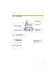
Operating Instructions 1 Camera Monitoring 1Table of Contents 1.1 BB-HCM381A Feature Locations 1.1.1 Front View Auto Focus/Zoom Lens Wide: 5 mm (3/16 inches) —Infinity Tele: 1 m (3 feet 3 inches) —Infinity Indicator The indicator color shows camera status (see page 153). SD Memory Card Cover Protects the SD Memory Card from dust. Remove the cover only when removing the SD Memory Card (see page 140).
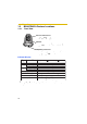
Operating Instructions 1.1.2 Rear View External I/O (See page 164) Ethernet (LAN) port Connects the camera to your LAN. Audio/Video terminal (See Getting Started) 1.1.3 DC IN jack Connects the camera to the AC adaptor. Hook for AC Adaptor Cord Used to secure the AC adaptor cord. Bottom View FACTORY DEFAULT RESET button Resets settings to default (see page 166). MAC Address and Serial Number are indicated on the label. Hole for Ceiling Plate A Used for ceiling mounting (See Installation Guide).
Operating Instructions 1.2 BB-HCE481A Feature Locations 1.2.1 Front View Auto Focus/Zoom Lens Wide: 5 mm (3/16 inches) —Infinity Tele: 1 m (3 feet 3 inches) —Infinity Indicator The indicator color shows camera status (see page 153). SD Memory Card Cover Protects the SD Memory Card from dust. Remove the cover only when removing the SD Memory Card (see page 140).
Operating Instructions 1.2.2 Rear View External I/O (See page 164) PoE IN port Connects the camera to your PoE hub. Audio/Video terminal (See Getting Started) 1.2.3 Bottom View FACTORY DEFAULT RESET button Resets settings to default (see page 166). MAC Address and Serial Number are indicated on the label. Hole for Ceiling Plate A Used for ceiling mounting.
Operating Instructions 1.3 How to Turn on the Camera Connecting the AC cord (for BB-HCM381A) or the Ethernet cable (for BBHCE481A) turns the camera on, and disconnecting the AC cord (for BBHCM381A) or Ethernet cable (for BB-HCE481A) turns the camera off. BB-HCM381A • Connecting the plug of the AC cord to the outlet turns the camera on. • Disconnecting the plug of the AC cord from the outlet turns the camera off.
Operating Instructions 1.4 Accessing the Camera 1. Start up the web browser on your PC. 2. Enter "http://IPv4 Address (or URL):Port Number" on the address bar, and press [Enter] on the keyboard. • When the port number is 80 (default), you do not need to include the port number in the address. See page 50 for details about the port number. • For IPv6 connection, see page 15 and page 16, and confirm that your equipment meets the requirements.
Operating Instructions 4. Click the following tabs to display each page. A B C D E F G Select a language Version Number Displays IPv4, IPv6 or IPsec connection.
Operating Instructions 1.4.1 To Access the Camera in IPv6 You need to prepare the following to access the camera in IPv6. • PC Requirements Operating System: Windows XP Service Pack 1 or later Web Browser: Internet Explorer 6.0 or later • An IPv6 Router • An IPv6 Connection Service To connect in IPv6, subscribe to the ISP's "IPv4/IPv6 Dual-Stack" or "IPv6 over IPv4 Tunneling" service. The camera does not function on IPv6-only networks.
Operating Instructions Setting up your PC 1. Click [Start] • [All Programs] [Accessories] [Command Prompt]. The Command Prompt window is displayed. 2. Enter "ipv6 install". • "Succeeded" is displayed. Note • If Windows XP Service Pack 1 or later is not installed, "Succeeded" will not be displayed. Install it on your PC.
Operating Instructions 1.5 Viewing the Single Camera page 1. Access the camera (see page 13). • The Top page is displayed. 2. Click the [Single] tab at the top of the page. • When the Security Warning window is displayed, click [Yes] (see page 19). • See page 20 for the Security Warning window when using Microsoft® Windows® XP Service Pack 2.
Operating Instructions • When displaying video (Motion JPEG), the camera allows up to 30 simultaneous accesses. The 31st user trying to access will see a gray screen. The Buffered Image page is also limited to a maximum of 30 simultaneous accesses. • To reduce the data traffic, the video can be automatically changed to refreshing still images on the General User page (see page 93). • To display the Single Camera page directly, add it to the [Favorites] on the web browser.
Operating Instructions Security Warning window When trying to view a video (Motion JPEG) for the first time, a Security Warning for ActiveX® Controls will be displayed. When using Windows 2000 or Windows XP, log in as an administrator to install ActiveX Controls and enable video viewing. If you cannot install ActiveX Controls or you cannot see the video using the Internet Explorer • In Internet Explorer, click [Tools] [Internet Options] [Security] tab and click [Custom level].
Operating Instructions Security Warning window on Microsoft Windows XP Service Pack 2 To view a video (Motion JPEG) or to use audio feature, ActiveX Controls must be installed. Follow the steps shown below to install ActiveX Controls. 1. Click the warning displayed above the tabs, and click [Install ActiveX Control...]. 2. Click [Install]. ******** 1.5.1 Displaying the Banner An image and its linked website can be specified for a banner.
Operating Instructions 1.5.2 Auto Centering the Image (Click to Center) Using your mouse, click any portion of the camera image. As long as it is within the pan/tilt range of the camera, the image will automatically move to place the selected point in the center of the screen. 1. Move the cursor to the desired point. Cursor 2. Click it. • • The clicked point is centered. See page 25 for the pan/tilt operation.
Operating Instructions 1.5.3 Capturing a Still Image Still images can be saved on your PC. 1. Operate pan/tilt and select a resolution to display an image. 2. Click the capture image button. Capture Image Button • The camera image opens in another window. 3. Right-click the image, and select [Save Picture As...]. • The Save as dialog box is displayed. 4. Specify a folder, enter the file name and click [Save]. • The camera image is saved at that location. 5. Click [Close].
Operating Instructions 1.5.4 (1) (2) (3) (4) (5) (6) Using the Operation Bar (1) End Display and Preset Display: When the pan/tilt has reached the end of its range, the End Display (Left End, Right End, Up End or Down End) appears. When the zoom or focus operation has reached the end, Wide End, Tele End, Near End, or Far End appears. When you select a preset, the preset name appears.
Operating Instructions (7) Brightness: Adjusts image brightness in 9 steps including [STD] (Standard). Clicking [-] or [+] changes the image brightness. (8) Output Control: Controls the output signals of the External I/O. (9) Refresh Interval: Sets a refresh interval. (Motion— 60-second interval) (10) Resolution: Selects [640 x 480] or [320 x 240] (default) pixels. (11) Image Quality: Selects the image quality. (7) (8) (9) (10) (11) 24 • [Favor Clarity] optimizes the image for good clarity.
Operating Instructions Pan/Tilt Operation The pan scan and tilt scan buttons automatically move the lens horizontally from -175° to +175° and vertically from -120° to 0° in mounting on the table and from 0° to +90° in mounting on the ceiling, and the lens returns to the current position. Use Click to Center feature to stop scanning. Each pan/tilt arrow moves the lens Up, Down, Right, Left, and the home position button moves it to Home Position.
Operating Instructions 1.5.5 Zooming In and Out Network Camera has a 42x magnifying capacity: the 21x magnifying capacity of the optical zoom and 2x magnifying capacity of the digital zoom. You can use the zoom buttons in the Operation Bar or your mouse to zoom in or out on increase or decrease the size of the object on the Single Camera screen. The zooming feature has 12 steps (10 steps of Optical Zoom and 2 steps of Digital Zoom). Using the zoom buttons Tele button zooms in, and Wide button zooms out.
Operating Instructions Note • Zoom control can be enabled or disabled for General Users and Guest Users (see page 93). If disabled, a 10x digital zoom is available. • The performance of the mouse varies according to your OS. • The optical zoom automatically switches to the digital zoom. • The definition in the image may decrease when using the digital zoom. • The position you click may considerably deviate from the center of the image when using the Click to Center feature on a large zoom scale.
Operating Instructions 1.5.6 Automatic and Manual Focusing Focus button adjusts the focus. Network Camera has Automatic and Manual Focusing features. AF (Automatic Focus) button automatically allows the lens to focus on objects. Manual focusing starts by pressing Near or Far button. Near button enables the lens to shorten the focal distance, and Far button lengthens it, manually. Manual focusing feature has 40 steps.
Operating Instructions • Fingerprints, dust, stains, etc. on the lens can degrade the performance of the Automatic Focusing feature. Wipe the lens with lens cleaning paper. • The image may be out of focus, if it is too near, or depending on the zoom position. Move the object, or adjust the zoom position. • The access level for the zoom feature can be set (see page 93). If the zoom feature is not permitted, the x10 digital zoom feature is available.
Operating Instructions 1.5.7 Setting Home Position/Alarm Position/Preset Position Registering Home Position/Alarm Position A home position or 2 alarm positions can be registered. When restarted, the camera takes a home position. If the Lens Position When Triggered setting is set for buffering images by alarm (see page 107) or by motion detection (see page 119), the camera moves to the alarm position when triggered. 1. Click [Program]. [Program] switches to [Cancel].
Operating Instructions Registering a Preset Position 20 camera positions can be stored as presets. These positions can be changed (see page 33). • Registered buttons are shown in blue. • Unregistered buttons are shown in white. 1. Click [Program]. • [Program] switches to [Cancel]. Click [Cancel] to quit without saving changes. 2. Pan and tilt the camera to a desired Pan/Tilt position. 3. Zoom to the desired position. 4. Adjust the focusing if necessary. 5.
Operating Instructions Viewing the Image 1. Select the home position, alarm position or a registered preset button or position. • The camera moves to that position and the image is displayed. Home Position Pan/Tilt Placing the cursor over the button displays the preset name.
Operating Instructions Changing or Deleting the Settings 1. Click [Program]. • [Program] switches to [Cancel]. Click [Cancel] to quit without saving changes. Home Position 2. Pan and tilt the camera to a desired Pan/Tilt Zoom position, or skip to step 5 if deleting a preset. 3. Zoom to the desired position. 4. Adjust the focusing if necessary. 5. Select the home position, alarm position or a registered preset position button (1—8) or (1—20). Note • All the items can be selected from drop-down list.
Operating Instructions 1.6 Listening to Camera Audio and Talking through the Camera 1. Access the camera (see page 13). • The Top page is displayed. 2. Click the [Single] tab at the top of the page. 3. The Audio Control Bar (Talk Button, Listen Button and Adjustment Bar) is displayed at the top of the screen. Listening mode and talking mode are selected using the relevant icons. This feature is only displayed for general users when it is enabled.
Operating Instructions Note • An external microphone and speaker must be connected to the camera (via the Audio/Video Cable) in order to use the Listen and Talk buttons. • The Talk button and Listen button cannot be used simultaneously. The Talk feature is stopped during listening. The Talk feature can be used by only one user at a time. The Listen feature can be used by a maximum of 10 users simultaneously. If the audio breaks up, reduce the maximum bandwidth (see page 48 or page 53).
Operating Instructions 1.7 Viewing the Multi-Camera page To view multiple cameras on the Multi-Camera page, you need to configure each camera on the Multi-Camera Setup page (see page 148). 1. Access the camera (see page 13). • The Top page is displayed. 2. Click the [Multi] tab at the top of the page. • The Multi-Camera page can display up to 12 camera images. Capture Image Button (See page 22) Switches displayed cameras.
Operating Instructions Note • When selecting [All] for the View Type, all images are displayed in 160 x 120 pixels resolution, and the Audio Control Bar is not displayed. • 640 x 480-pixel images cannot be displayed on the Multi-Camera page. • When viewing video (Motion JPEG), we recommend using an Ethernet switching hub instead of a repeater hub to prevent degradation in video display. • Due to network congestion or the number of accesses, the refresh interval may increase.
Operating Instructions 1.8 Viewing the Buffered Image page To buffer images in the camera's internal memory, you need to set up the image transfer settings (see page 97, page 107, or page 119). Buffered images can be viewed on this Buffered Image page. Note • Sound cannot be buffered on the Buffered Image page. 1. Access the camera (see page 13). • The Top page is displayed. 2. Click the [Buffered Image] tab at the top of the page. 3. Click the trigger number.
Operating Instructions 4. Display images by clicking buttons below. The date and time when the images were buffered are displayed. The date, time and frame number are displayed. [Play]: The buffered images are displayed in sequence. []: The previous or next image is displayed. [First], [<1000], [<100], [<10] or [10>], [100>], [1000>], [Last]: The first or last image, or the 10th, 100th or 1000th image before or after the current image appears.
Operating Instructions Using the zoom feature on the Buffered Image page • The optical zoom is not available while playing back buffered images with the [Play] button, however a 10x digital zoom is available. You can zoom in and out using the mouse or scroll wheel (see page 26). • The zoom depth (x1.0—x10.0) is displayed while zooming. • As the magnification increases, the image quality decreases. Note • The buffered images are displayed chronologically.
Operating Instructions 1.9 Viewing Still Images on Your Cell Phone Still images can be viewed over the Internet from a compatible cell phone. Enter "http://IP address (or URL):Port Number/Mobile" on a cell phone and press [OK]. • When the port number is set to 80 (default), it is not required. E.g. http:// (or • • • . . . :50000/Mobile .viewnetcam.com:50000/Mobile) Access to the camera from cell phones must be allowed.
Operating Instructions (1) Pressing 2, 4, 6 or 8 on the cell phones allows you to pan or tilt the camera in four directions: Left, Up, Down or Right. (2) Pressing allows you to zoom in, and pressing # allows you to zoom out. (1) (2) (3) (4) (5) (3) Pressing 5 will refresh the image. (4) 160 x 120 resolution is displayed on the first access. Pressing 0 switches the resolution to 320 x 240. (6) (5) Executing [Home Position] moves the lens to the home position.
Operating Instructions (10) Goes to the control page. (11) Displays the number of new logs. (12) Displays the date and time, the kind of signal and sensor. (10) Display Operation (11) A1 R Alarm1 A2 F Alarm2 MD Motion Detection (12) (13) Signal Rising: GND to Open (High) Falling: Open (High) to GND - (13) Goes to the control page. Note • Audio feature does not work on cell phones.
Operating Instructions 1.9.1 Enabling or Disabling the Buffer/Transfer on your Cell Phone 1. Access camera images from your cell phone, and log in as an administrator. 2. Select [Buffer/Transfer]. 3. Select a trigger number that you want to enable or disable. Example: Enabling the Buffer/Transfer setting (No.1). • Selecting [Control Page] changes to the previous page. 4. Select [Save]. • • 44 Selecting [Save] enables or disables the buffer/transfer settings, and all buffered images will be deleted.
Operating Instructions 2 Using the Camera's Basic Features 2.1 Setup Page of the Camera 1. Access the camera (see page 13). • Note • • • The Top page is displayed. When [Permit access from guest users] is set on the Security: Administrator page, click the [Login] tab and log in as an administrator. When users other than an administrator are accessing the camera, the [Setup] and [Maintenance] tabs are not displayed.
Operating Instructions Basic 46 (1) Network (IPv4) Configures the IPv4 network settings to connect the camera to the network (see page 48).
Operating Instructions (15) Multi-Camera*1 Sets the camera IP address or host name, and camera name on the Multi-Camera page (maximum 12 cameras) (see page 148). (16) Operation Time Sets the time period to display camera images (see page 150). (17) External Output Sets the external output terminal of the External I/O (see page 152). (18) Indicator Control Sets the indicator display (see page 153).
Operating Instructions 2.2 Connecting the Camera to Your IPv4 Network The Network page offers three options to configure the camera in IPv4. • [Automatic Setup] automatically assigns an unused IP address to the camera, and uses UPnP™ (Universal Plug and Play) to configure your router. • [Static] allows the user to use a specific IP address. • [DHCP] is offered for ISPs that require this option. 1. Click [Network (IPv4)] on the Setup page. 2. Click a connection mode. Most common mode of setup.
Operating Instructions DHCP Setup • Static Setup Clicking [Cancel] takes you back to the previous page without saving changes. 4. Click [Save] when finished. • • Note • The new settings are saved. When finished, the following page is displayed. The current network settings are shown on the Status page in the Maintenance section (see page 155). 5. Click [Restart]. • • Note • The camera restarts, and the Top page is displayed.
Operating Instructions • When the camera is restarted, all buffered images in the internal memory are deleted. The buffered images on the SD memory card are not deleted. Setting Allow Access from the Internet (Automatic Setup Only) Description • Network • Configuration from Setup Program (Static/DHCP Only) To prohibit the Setup Program from changing the network settings, uncheck the box. Port Number • (Static/DHCP Only) The default port number is 80.
Operating Instructions Setting Host Name (DHCP Only) Description • • Default Gateway*1 • (Static/DHCP Only) • • DNS Server Address*1 (Static/DHCP Only) • • Max. Bandwidth Usage • • • If your ISP uses the DHCP function, which automatically assigns an IP address to the camera, enter the ISP–assigned host name. (The host name may be used as an authentication.) Enter ASCII characters for the host name (see page 190). Note that [Space], ["], ['], [&], [<] and [>] are not available.
Operating Instructions Setting Connection Type Description • • Select [Auto Negotiation] normally. If the camera cannot be accessed, see page 9 of the Troubleshooting on the CD-ROM. This setting is valid in both IPv4 and IPv6. *1 If the IP address is automatically obtained from a DHCP server, this field does not need to be set.
Operating Instructions 2.3 Connecting the Camera to Your IPv6 Network The Network page offers two options to configure the camera in IPv6. • [Automatic Setup] automatically assigns an IPv6 address to the camera. • [Static] allows the user to use a specific IPv6 address. Note • IPv6 is an expanded protocol created for future Internet expansion. Your network and your ISP must support IPv6 before you can use this feature. 1. Click [Network (IPv6)] on the Setup page. 2. Click a connection mode.
Operating Instructions Static Setup You can assign a static IPv6 address to the camera. If you select [No] for Allow Access from the Internet, the camera can be accessed only from the LAN that has an same IPv6 prefix as the camera. • Clicking [Cancel] takes you back to the previous page without saving changes. 4. Click [Save] when finished. • • Note • The new settings are saved. When finished, the following page is displayed.
Operating Instructions Setting Allow Access from the Internet Description • If [Yes] is selected for Allow Access from the Internet, you can access the camera from the Internet. If [No] is selected, the camera can be accessed only from a LAN that has an same IPv6 prefix as the camera. Port Number (Static • Only) • The default port number is 80. A unique port number must be set for each terminal on your network. Do not set the following port numbers.
Operating Instructions Setting Max. Bandwidth Usage Description • • • The bandwidth can be restricted. Select a maximum bandwidth from [Unlimited] to [0.1 Mbps]. This setting is valid in both IPv4 and IPv6. Note • Set a maximum bandwidth referring to the following file sizes. These are examples for a JPEG file of standard image quality. File sizes may change depending on the image quality or the brightness of the object. – 160 x 120 pixels: About 3.
Operating Instructions 2.4 What is IPsec? IPsec provides security for the transmission of sensitive information over unprotected networks such as the Internet. IPsec authenticates IP packets between participating IPsec devices. Unreadable Malicious User Image Allowed User Internet Readable Camera's IPsec Features The camera can use IPsec in both IPv4 and IPv6. The camera supports the following IPsec features.
Operating Instructions IPsec Mode Selection Select transport mode or tunnel mode to access the camera. Transport Mode (IPv4 Only) The image is encrypted for the whole way between the camera and your PC. The transport mode is available only in IPv4 for users of Windows XP Service Pack 1 or later. Transport Mode Encrypted Prepare the following required items: Item PC Supported Feature Operating System : Windows XP Service Pack 1 or later Web Browser : Internet Explorer 6.
Operating Instructions Tunnel Mode (IPv4/IPv6) An IPsec mode of operation where the entire IP packet including IP header is authenticated and encrypted. A new IP header is added (protecting the entire original packet). Both VPN clients and VPN gateways can use this mode. Note • The camera can be accessed only from PCs under the VPN router. Other PCs cannot access the camera.
Operating Instructions 2.5 Encrypting the Camera Image in Transport Mode The camera can encrypt images using IPsec transport mode. Note • If you use IPsec, the refresh interval increases. 1. Click [IPsec] on the Setup page. 2. Click Camera in the Transport column. • If you use transport mode for E-mail or FTP transfer, click No. in the Buffer/ Transfer column. Set to use Alarm Log.
Operating Instructions Setting Description Status • Check the box to use this encryption method. Pre-Shared Key • This is the key used in the authentication of communications. Enter the same pre-shared key as your PC. Enter ASCII characters for the host name (see page 190). But [Space], ["], ['], [&], [<] and [>] are not available. • Note • If the pre-shared key becomes known to a third party, it may lead to illegal access, a leak of private information or interference.
Operating Instructions 7. Click [Restart]. 8. Set up your PC according to the requirements on page 58. • Set the FTP server or E-mail server to transfer images. 9. Access the camera (see page 13). • Note • • • 62 If you can access the camera, the IPsec setup is complete. In IPsec communications, "IPsec" is displayed on the Top page or the Single Camera page. If you cannot communicate using IPsec, see page 24 of Troubleshooting on the CD-ROM.
Operating Instructions 2.6 Encrypting the Camera Image in Tunnel Mode The camera can encrypt images using IPsec tunnel mode. Note • Do not set IPsec on PCs under the VPN router. Communications may be blocked. If you use IPsec, the refresh interval increases. The camera can be accessed only from PCs under the VPN router. Other PCs cannot access the camera. • • 1. Click [IPsec] on the Setup page. 2. Click Add in the Tunnel column. 3. Enter each parameter in the relevant data field.
Operating Instructions Setting Pre-Shared Key Description • • This is the key used in the authentication of communications. Enter the same pre-shared key as your VPN router. Enter ASCII characters for the host name (see page 190). But [Space], ["], ['], [&], [<] and [>] are not available. Note • If the pre-shared key becomes known to a third party, it may lead to illegal access, a leak of private information or interference. To protect your security and privacy, pay attention to the following points.
Operating Instructions Setting Description IPsec • Check the box to enable IPsec features. If you uncheck the box, all IPsec features will be invalid. Encoding strength • The encoding strength for IPsec can be selected. If you select [Standard], DES or NULL is valid as an algorithm, and the data will become easier to decrypt. 7. Click [Restart]. 8. Set up your VPN router as shown below. • To use tunnel mode, you need to set up your VPN router.
Operating Instructions • Set up the IPsec policy as below. Items Settings Protocol ANY Source Network Network address and subnet mask on the LAN side of the VPN router Source IP address A global address on the WAN side of the VPN router Destination Network A global address of the camera Destination IP address A global address of the camera 9. Access the camera (see page 13). • Note • • • 66 If you can access the camera, the IPsec setup is complete.
Operating Instructions Using UPnP™ (Universal Plug and Play) 2.7 UPnP™ can automatically configure your router to make it accessible from the Internet. In order to use this feature, your router needs to support UPnP™, and it must be enabled. UPnP™ is disabled on most routers by default. Most router manufacturers disable this feature as the default setting. See http:// panasonic.co.jp/pcc/products/en/netwkcam/ and your router's manual for details of how to enable UPnP™.
Operating Instructions 4. Click [Go to UPnP page]. • 2.7.1 The UPnP page is displayed. Connecting the Camera to a Router that Supports UPnP™ (IPv4 Only) To allow access from the Internet with a router supporting UPnP™, follow the procedures shown in Getting Started. Note • • 2.7.2 On some routers, the UPnP™ feature is disabled by default. Enable your router's UPnP™ feature following the router manual before you set up the camera. See the Panasonic Network Camera support website at http:// panasonic.
Operating Instructions Port Forwarding feature*1 (IPv4 Only) The port forwarding feature is required to allow camera access from the Internet with a router that does not support UPnP™. It exchanges a local IP address for a global one. Global IP address of the router vvv.xxx.yyy.zzz:80 vvv.xxx.yyy.zzz:81 Port Forwarding feature Port No. vvv.xxx.yyy.zzz:80 vvv.xxx.yyy.zzz:81 192.168.0.253:80 192.168.0.252:81 Router Modem 192.168.0.1 Local IP address Note • *1 192.168.0.252 192.168.0.253 Port No.
Operating Instructions 2.8 Registering with the DynamicDNS Service DynamicDNS is a service that allows you to assign an easy-to-remember name to the camera, for example, similar to your favorite web site. It also allows you to easily access the camera, even when your ISP changes the IP address. Panasonic Communications recommends that you register with a DynamicDNS to access the camera from the Internet. See http://www.viewnetcam.
Operating Instructions 3. Click [Save]. • Clicking [Cancel] cancels your settings without saving changes, and the DynamicDNS window is displayed. Setting Description Personal (Camera) URL • The camera's personal URL will be displayed after you register with the Viewnetcam.com service. Your Account Link • The URL required to register with the Viewnetcam.com service is displayed. Clicking [Your Account Link] item name displays the Viewnetcam.com registration website. 4. Click [OK].
Operating Instructions 7. Register with the Viewnetcam.com service following the instructions on the website. • The Viewnetcam.com page is displayed. 8. Access your camera with the registered URL from the Internet (see page 13). • Note • • When the Top page is displayed, Viewnetcam.com registration is complete. It may take a maximum of 30 minutes for the registered URL to work. If "Expired" is displayed for the Personal (Camera) URL on the Viewnetcam.com page or for the Camera URL at Viewnetcam.
Operating Instructions 3. Set each parameter. • • Clicking [Cancel] cancels your settings without saving changes. DynamicDNS information can be obtained from companies in the DynamicDNS service industry. Setting Description DynamicDNS Server URL*1 Input URL acquired from the DynamicDNS service industry company. Enter up to 255 characters. The URL must be started with "http://". Updating time Specify the updating time.
Operating Instructions Confirming Internet access Due to the router’s specifications, the image may not be displayed even if you access the camera from your PC on the same LAN as the camera.
Operating Instructions 2.8.1 DynamicDNS Service (IPv4/IPv6) DynamicDNS allows you to choose an easy-to-remember address (such as "bob.viewnetcam.com") that can be used to view images from your camera over the Internet. This service is compatible with both IPv4 and IPv6 addresses. Some DynamicDNS service is not compatible with IPv6 address. What are the advantages of DynamicDNS service? In order to view camera images over the Internet, you need to know your camera's global IP address.
Operating Instructions 4. When you enter your DynamicDNS address in your web browser while away from home or the office, the DNS server looks up the global IP address assigned to your DynamicDNS address. 5. The DNS server finds your current global IP address and allows you to connect to your camera. Note • • • 76 Ask your ISP about what type of IP address you are using. Some ISPs assign you a local IP address. In this case, the DynamicDNS service cannot be used.
Operating Instructions 2.9 Setting the Date and Time The Date and Time page allows you to set and confirm the date and time. The date and time are used for the settings of the trigger setting, alarm log, operation time and Buffered Image page. Note • Saving a new date and time deletes all buffered images on the internal memory. The buffered images on the SD memory card are not deleted. 1. Click [Date and Time] on the Setup page. 2. Set each parameter.
Operating Instructions Setting Time Setting Description • Set the date and format (AM/PM or 24 H). The interface and available values depend on the format. The date and time are used for the settings of the trigger setting, sensor log, operation time and Buffered Image page. Note that the format for the subject and file name of E-mails by E-mail or FTP transfer can only be 24 h.
Operating Instructions 4. Click [Go to Date and Time page]. • Note • The Date and Time page is displayed. Date and time settings become incorrect depending on the length of time the camera is turned on and its internal temperature. Using the Automatic Time Adjustment is recommended.
Operating Instructions 2.10 Changing Camera Settings The Camera page allows you to set the camera name, white balance, AC power source frequency, automatic focus range, mounting type, pan/tilt range, return to specified position, color night view, and vertical resolution settings. 1. Click [Camera] on the Setup page. 2. Set each parameter. • 80 Clicking [Cancel] cancels your settings without saving changes.
Operating Instructions Setting Camera Name Description • • White Balance The camera name is displayed on the Single Camera page. Enter ASCII characters (see page 190) or characters from other languages (1—15 characters for a 1-byte character and 1—7 characters for a 2-byte character). Note that [Space], ["], ['], [&], [<], and [>] are not available. Select from the following options. "K (Kelvin)" is a unit for color temperature.
Operating Instructions Setting Pan Range*1 Description Select from the following options. • Minimum — Current settings, -175—+175 • Home Position — Current settings, -175—+175 • Maximum — Current settings, -175—+175 *2 The values must be selected as minimum home position maximum. Note • Tilt Range*1 Your privacy may be compromised if the range is set incorrectly. Check the range after setup. Select from the following options.
Operating Instructions Return to Specified Position • • If the camera is not operated during the specified period, the camera turns to a specified position. The following settings are available: – Time: Do not move, 10 s, 20 s, 30 s, 1 min, 5 min, 10 min, 30 min, 1 h – Specified Position: Home Position, Preset No.1— 20, Alarm No. 1, Alarm No. 2 Note Color Night View • • • A preset position (1—20) is displayed as a ("preset number"."preset name"). (e.g.: 1.
Operating Instructions 3. Click [Save] when finished. • • The new settings are saved. If the [Pan Range] or [Tilt Range] settings are changed, the camera turns to the home position. When finished, "Success!" is displayed. 4. Click [Go to Camera page]. • The Camera page is displayed. Specifying the Pan/Tilt Range 1. Access the camera (see page 13), and click [Single] at the top of the Top page. 2. Open another web browser, and display the Camera page (see page 80). 3.
Operating Instructions Note • The values must be selected as minimum home position maximum. When the camera is mounted on a table When the camera is mounted on a ceiling Max.: 0 ˚ Max.: +90 ˚ Min.: -175 ˚ Max.: +175 ˚ Min.: -120 ˚ Max.: +175 ˚ Min.: -175 ˚ Min.: 0 ˚ 5. Click [Save] on the Camera page. • The new settings are saved. The camera turns to the home position.
Operating Instructions 2.11 Adjusting Audio The Audio page allows you to set the microphone, the external speaker, microphone sensitivity and external speaker volume settings. 1. Click [Audio] on the Setup page. 2. Set each parameter. • Clicking [Cancel] cancels your settings without saving changes. Setting 86 Description Output • You can control audio output for the external speaker connected to the camera. Volume • You can control the external speaker output volume.
Operating Instructions Setting Mute during Pan/Tilt • Description You can temporarily turn off the audio (audio input) when the camera pans or tilts. 3. Click [Save] when finished. • • The new settings are saved. When finished, "Success!" is displayed. 4. Click [Go to Audio page]. • The Audio page is displayed.
Operating Instructions 3 Registering Users 3.1 Changing the Authentication Setting and Administrator User Name and Password The Security: Administrator page allows you to change authentication, and the administrator's user name and password. An authentication window allows registered users to access the camera. Note • If you access the camera for the first time, the window for setting the administrator's user name and password is displayed.
Operating Instructions 1. Click [Administrator] on the Setup page. 2. Set each parameter. • Clicking [Cancel] cancels your settings without saving changes. Setting General Authentication Description Authentication has 3 phases. • If you set [Permit access from guest users], the camera does not display the authentication window in camera access. All guest users can view images without a user name and password.
Operating Instructions Setting User Name/ Password Description • • User Name (6 to 15 characters): Enter the user name. Password (6 to 15 characters): Enter the password. Note • The password must be different from the user name. • Retype Password: Reenter the password. • Enter ASCII characters (see page 190). Note that [Space], ["], ['], [&], [<], [>] and [:] are not available. Note • • • When setting authentication, set the user name and password, and save them.
Operating Instructions Administrator/General Users/Guest Users The access level to the camera is divided to administrator, general users and guest users.
Operating Instructions 3.2 Logging in to the Camera If you set [Permit access from guest users] on the Security: Administrator page, [Login] is displayed at the top of the page. After you log in as an administrator, the Setup page and the Maintenance page can be accessed. 1. Click [Login] at the top of the page. 2. Check a login mode, and click [Login]. Note • The authentication window is displayed. Enter the user name and password set for General Users or Administrator. 3.
Operating Instructions 3.3 Creating, Modifying or Deleting General Users The General User page allows you to create, modify or delete general users. Up to 50 general users can be registered. The access level is set for each general user. If you set [Permit access from guest users] or [Permit access from guest users (mobile only)] on the Security: Administrator page, the access level can be set for guest users. Note • For general users, the Setup and Maintenance tabs are not displayed. 1.
Operating Instructions 3. Set each parameter. • Settings for general users • Clicking [Cancel] takes you back to the previous page without saving changes. Setting • Settings for guest users Description User ID List • • Up to 50 general users can be registered. The list is used to modify or delete general user settings. User Name/ Password • • User Name (6 to 15 characters): Enter the user name. Password (6 to 15 characters): Enter the password.
Operating Instructions Setting Access Level Description An access level is set for each general user. Check each feature to enable access to it. • In the limit time of continuous Motion JPEG setting, set the time for changing video (Motion JPEG) to still images for each user. (Not permitted, Unlimited, 10 seconds—60 minutes) In the refresh interval setting, set the refresh interval after the video has changed to still images.
Operating Instructions 4 Buffering or Transferring Images 4.1 Procedures of Buffering or Transferring Images The procedures from this page to page 130 are described about settings of the image buffer or transfer. See the procedures below to understand the general outline of the settings.
Operating Instructions 4.2 Buffering or Transferring Images by Timer The Trigger page allows you to enable image buffer/transfer by E-mail or FTP. Note • If you are recording images to the SD memory card, refresh interval slows down. 1. Click [Trigger] on the Setup page. 2. Click a No. to enable buffer/transfer. 3. Check [Enable Image Buffer/Transfer], select [Timer] for the trigger, and click [Next>]. • • • Note • Click [Delete Buffered Images] to delete images already buffered.
Operating Instructions Setting Trigger Description • • • Selecting [Timer] enables the camera to buffer/transfer images by timer. Selecting [Alarm 1 or 2] enables the camera to buffer/ transfer images by alarm signal. Selecting [Motion Detection] enables the camera to buffer/ transfer images when the motion is detected. 4. Set the time, and click [Next>]. Note The timer works by an internal clock. Set the date and time before using timer buffer/transfer (see page 77).
Operating Instructions Setting Description Image Resolution • Image Quality • Select an image resolution (640 x 480, 320 x 240 (default) or 160 x 120 pixels) for the buffer/transfer. Select the image quality. [Favor Clarity] optimizes for good quality. [Standard] offers standard quality. [Favor Motion] optimizes for enhanced motion. [Mobile Phone] is for a transfer to a cell phone. Note • 640 x 480 pixels cannot be set for a transfer to a cell phone. 6.
Operating Instructions 7. Select the transfer method, and click [Next>]. • • Note • Clicking [
Operating Instructions When you set [FTP] for Transfer Method Select [FTP], and click [Next>]. The following page is displayed. • • Clicking [
Operating Instructions Setting Description Overwrite Setting • Selecting [Overwrite File] overwrites the image on the server with a newer image. Selecting [Save as New File with Time Stamp] saves the image attaching time stamps on the file name, and the images are not overwritten. E.g. image20050101093020500.jpg The underlined numbers mean "9h30min20s500ms on January 1, 2005". The letter "s" is inserted after the day when referring to a daylight saving time zone.
Operating Instructions When you set [E-mail] for Transfer Method Select [E-mail], and click [Next>]. The following page is displayed. • • Clicking [
Operating Instructions Setting Description SMTP Server IP • Address or Host Name*1 104 • If you set a server IP address, set 4 numbers (0—255) and 3 periods such as "192.168.0.253". Note that "0.0.0.0" and "255.255.255.255" are not available. Or set a host name (1—255 characters). You can set an IPv6 address. Port No. • Enter the number (1—65535). Usually set to 25. Reply E-mail Address*2 • Set the sender's E-mail address. We recommend you to set the administrator's E-mail address.
Operating Instructions Setting How to authenticate Description The authentication method can be selected: [No authentication], [POP before SMTP authentication] or [SMTP authentication]. POP server authentication may be required by your ISP. In that case, set POP before SMTP authentication. • No authentication: No authentication when sending an email. • POP before SMTP authentication: Some SMTP servers that send e-mails do not have an authentication feature.
Operating Instructions 8. Confirm the settings, and click [Save]. • • The new settings are saved. When finished, "Success!" is displayed. 9. Click [Go to Trigger page]. • The Trigger page is displayed. Note • If you click [Save] on the Trigger page, all buffered images on the SD memory card are deleted. • If you are buffering images to the internal memory, the following operations also delete all buffered images. – Turning off or restarting the camera. – Updating the camera.
Operating Instructions 4.3 Buffering or Transferring Images by Alarm Signal You can buffer the camera images, transfer to an FTP server or send E-mails using alarm as a trigger. The Trigger page allows you to enable image buffer/transfer by E-mail or FTP. Note • If you are recording images to the SD memory card, refresh interval slows down. • To buffer/transfer images by alarm signal, an alarm must be connected to the external I/O (see page 164). 1. Click [Trigger] on the Setup page. 2. Click a No.
Operating Instructions Setting Description Enable Image Buffer/Transfer • Check the box to enable the buffer/transfer. Uncheck the box to disable it. Trigger • Selecting [Timer] enables the camera to buffer/transfer images by timer. Selecting [Alarm 1 or 2] enables the camera to buffer/ transfer images by alarm signal. Selecting [Motion Detection] enables the camera to buffer/ transfer images when the motion is detected.
Operating Instructions 5. Set the Lens Position When Triggered setting, and click [Next>]. • • Note • Clicking [
Operating Instructions Setting Image Quality Description • Select the image quality. [Favor Clarity] optimizes for good quality. [Standard] offers standard quality. [Favor Motion] optimizes for enhanced motion. [Mobile Phone] is for a transfer to a cell phone. Note • 640 x 480 pixels cannot be set for a transfer to a cell phone. 7. Set the image buffer frequency, and click [Next>]. • • Note • • Clicking [
Operating Instructions Setting Enable Posttrigger Image Buffer Description • • Check the box to enable the setting. The camera buffers or transfers the image right after the alarm signal is detected. Set an interval, number of images to buffer and total number. The number of buffered images may not match the total number (see page 191) due to memory capacity, image resolution, image quality or what object you view. 8. Select the transfer method, and click [Next>].
Operating Instructions When you set [FTP] for Transfer Method Select [FTP], and click [Next>]. The following page is displayed. • • Clicking [
Operating Instructions Setting Description Overwrite Setting • Selecting [Overwrite File] overwrites the image on the server with a newer image. Selecting [Save as New File with Time Stamp] saves the image attaching time stamps on the file name, and the images are not overwritten. E.g. image20050101093020500.jpg The underlined numbers mean “9h30min20s500ms on January 1, 2005”. The letter “s” is inserted after the day when referring to a daylight saving time zone.
Operating Instructions When you set [E-mail] for Transfer Method Select [E-mail], and click [Next>]. The following page is displayed. • • Clicking [
Operating Instructions Setting Description SMTP Server IP • Address or Host Name*1 • If you set a server IP address, set 4 numbers (0—255) and 3 periods such as "192.168.0.253". Note that "0.0.0.0" and "255.255.255.255" are not available. Or set a host name (1—255 characters). You can set an IPv6 address. Port No. • Enter the number (1—65535). Usually set to 25. Reply E-mail Address*2 • Set the sender's E-mail address. We recommend you to set the administrator's E-mail address.
Operating Instructions Setting How to authenticate Description The authentication method can be selected: [No authentication], [POP before SMTP authentication] or [SMTP authentication]. POP server authentication may be required by your ISP. In that case, set POP before SMTP authentication. • No authentication: No authentication when sending an email. • POP before SMTP authentication: Some SMTP servers that send e-mails do not have an authentication feature.
Operating Instructions 9. After you confirm the settings and click [Next>], set E-mail notification and click [Next>]. • If you select [Enable], the E-mail Notification When Triggered page is displayed. Enter the settings referring to page 115—116. Setting Description Disable • The camera does not send an E-mail notification when buffering or transferring images. Enable • The camera sends an E-mail notification (up to 3 destinations) when buffering or transferring images. 10.
Operating Instructions • 118 If you are buffering images to the internal memory, the following operations also delete all buffered images. – Turning off or restarting the camera. – Updating the camera. – Resetting the camera to default. – Saving the Date and Time page.
Operating Instructions 4.4 Buffering or Transferring Images by Motion Detection Signal Camera has a Motion Detection feature that detects movement, such as people, based on the preset threshold and sensitivity of Camera. You can buffer the camera images, transfer to an FTP server or send E-mails using the Motion Detection function as a trigger. The Trigger page allows you to enable image buffer/transfer by E-mail or FTP.
Operating Instructions • • Click [Save] to save the settings. Clicking [Cancel] takes you back to the Trigger page without saving changes. Note • If you click [Save], all buffered images on the SD memory card are deleted. Setting Description Enable Image Buffer/Transfer • Check the box to enable the Trigger setting. Uncheck the box to disable it. Trigger • Selecting [Timer] enables the camera to buffer/transfer images by timer.
Operating Instructions 5. Set the image settings, and click [Next>]. • • Note • Clicking [
Operating Instructions Setting Image Quality Description • Select the image quality. [Favor Clarity] optimizes for good quality. [Standard] offers standard quality. [Favor Motion] optimizes for enhanced motion. [Mobile Phone] is for a transfer to a cell phone. Note • 640 × 480 pixels cannot be set for a transfer to a cell phone. 7. Set the image buffer frequency, and click [Next>]. fif • • Note • • Clicking [
Operating Instructions Setting Description Enable Post-trigger • Image Buffer • Check the box to enable the setting. The camera buffers or transfers the image right after the motion detection signal is detected. Set an interval, number of images to buffer and total number. The number of buffered images may not match the total number (see page 191) due to memory capacity, image resolution, image quality or what object you view. 8. Select the transfer method, and click [Next>].
Operating Instructions When you set [FTP] for Transfer Method Select [FTP], and click [Next>]. The following page is displayed. • • Clicking [
Operating Instructions Setting Description Overwrite Setting • Selecting [Overwrite File] overwrites the image on the server with a newer image. Selecting [Save as New File with Time Stamp] saves the image attaching time stamps on the file name, and the images are not overwritten. E.g. image20050101093020500.jpg The underlined numbers mean "9h30min20s500ms on January 1, 2005". The letter "s" is inserted after the day when referring to a daylight saving time zone.
Operating Instructions When you set [E-mail] for Transfer Method Select [E-mail], and click [Next>]. The following page is displayed. • • Note • • 126 Clicking [
Operating Instructions Setting Description SMTP Server IP • Address or Host Name*1 • If you set a server IP address, set 4 numbers (0—255) and 3 periods such as "192.168.0.253". Note that "0.0.0.0" and "255.255.255.255" are not available. Or set a host name (1—255 characters). You can set an IPv6 address. Port No. • Enter the number (1—65535). Usually set to 25. Reply E-mail Address*2 • Set the sender's E-mail address. We recommend you to set the administrator's E-mail address.
Operating Instructions Setting How to authenticate Description The authentication method can be selected: [No authentication], [POP before SMTP authentication] or [SMTP authentication]. POP server authentication may be required by your ISP. In that case, set POP before SMTP authentication. • No authentication: No authentication when sending an email. • POP before SMTP authentication: Some SMTP servers that send e-mails do not have an authentication feature.
Operating Instructions 9. After you confirm the settings and click [Next>], set E-mail notification and click [Next>]. • If you select [Enable], the E-mail Notification When Triggered page is displayed. Enter the settings referring to page 127–128. Setting Description Disable • The camera does not send an E-mail notification when buffering or transferring images. Enable • The camera sends an E-mail notification (up to 3 destinations) when buffering or transferring images. 10.
Operating Instructions • 130 If you are buffering images to the internal memory, the following operations also delete all buffered images. – Turning off or restarting the camera. – Updating the camera. – Resetting the camera to default. – Saving the Date and Time page.
Operating Instructions 4.5 Transferring Camera Images in Transport Mode The camera can transfer images in transport mode by E-mail or FTP. Transport Mode E-mail or FTP Server Encrypted Prepare the following required items: Item E-mail or FTP Server Camera Supported Feature Operating System : IPsec supported ISP Service : A service for multiple static global addresses (A global address must be set up to the server.
Operating Instructions 4.6 Transferring Camera Images in Tunnel Mode The camera can transfer images in tunnel mode by E-mail or FTP. E-mail or FTP Server VPN Router LAN WAN Not Encrypted Tunnel Mode Encrypted Prepare the following required items: Item VPN Router Camera Supported Feature ISP Service (in IPv4) : A service for static global addresses (A global address must be set up to the WAN side.
Operating Instructions 4.7 Setting the Motion Detection The Motion Detection page allows you to adjust the sensitivity of Motion Detection. Threshold: If the threshold is set low, this function detects nearly all movements. Sensitivity: If you set sensitivity high, the amplitude of the motion detection bar gets jumpy. 1. Click [Motion Detection] on the Setup page. 2. Click the Motion Detection bar in Threshold to set the threshold level. 3.
Operating Instructions Preview Display the current threshold and detection level. • The threshold is the line between the green and red bar. • The detection level is the line between the dark red and light red color. • The Threshold and Sensitivity settings are enabled after saving, and reflected in preview. • The Click to Center feature is available (see page 21).
Operating Instructions What is “threshold”? The threshold is the minimum value for the camera to detect motions on the image during the motion detection buffering. Setting the threshold lower allows subtler changes to be detected. Setting the threshold higher allows only bigger changes that might occupy half the image to be detected. What is “sensitivity”? The sensitivity is the level of brightness detected as motion by the camera.
Operating Instructions • 136 Additionally, if the object's color is similar to the color of the background, motion can be hard to detect. The detection level depends on the object, resolution, or image quality. Confirm the condition on the Preview window following the procedure above.
Operating Instructions 4.8 Setting Alarm Log Notification An alarm log sent once a day at a specified time can be checked. To enable Alarm Log, set Alarm 1, Alarm 2 or Motion Detection for Trigger Setting and check [Enable]. 1. Click [Alarm Log] on the Setup page. • When selecting Alarm1, Alarm2 or Motion Detection in Trigger page, the Alarm log window is displayed. 2. Set each parameter. 3. Click [Save]. • Clicking [Cancel] cancels your settings without saving changes. 4.
Operating Instructions Note • • When the settings are saved, the number of new alarm logs becomes 0. The camera works only with an SMTP (Simple Mail Transfer Protocol) server. It does not work with mail servers like "Hotmail" that use a web browser. Setting 138 Description A setup of operation • Alarm log operation can be set here. Time • Set the day of the week and time to send alarm logs via Email.
Operating Instructions Setting How to authenticate Description The authentication method can be selected: [No authentication], [POP before SMTP authentication] or [SMTP authentication]. POP server authentication may be required by your ISP. In that case, set POP before SMTP authentication. • No authentication: No authentication when sending an email. • POP before SMTP authentication: Some SMTP servers that send e-mails do not have an authentication feature.
Operating Instructions 4.9 Using the SD Memory Card The SD memory card (customer-provided) can store image data and replay them. Follow the instructions below to insert or remove the SD memory card. Note • • Format the SD memory card (see page 142) before you record the image data. The files recorded on the SD memory card can be viewed on your PC. Download the viewer software from the Panasonic Network Camera support website at http://panasonic.co.jp/pcc/products/en/netwkcam/ and install it on your PC.
Operating Instructions 3. Push the SD memory card with your finger until it clicks. When removing the card, push the card lightly to release it, then remove it from the slot. Note • • • Sound cannot be recorded. Ensure that recording has been stopped, before removing the SD memory card. If the SD memory card is removed while recording, the image file will most likely become unreadable. In this case, format the SD memory card again. (Files will be deleted.
Operating Instructions 4.9.1 Format the SD Memory Card Before you record the camera image, you need to format the SD memory card. Note • You can confirm the SD memory card capacity on the Status page. 1. Insert the SD memory card. 2. Click [Trigger] on the Setup page. 3. Click [Format]. 4. Click [OK] on the confirmation window. • Format is complete. 5. Click [Go to Trigger page]. • 142 The Trigger page is displayed.
Operating Instructions 4.9.2 Start the SD Memory Recording The SD memory recording can be started on the Trigger page. Note • • • You can confirm the SD memory card capacity on the Status page. If the camera is restarted, the SD memory recording starts again. If you remove the SD memory card and insert it again, the SD memory recording starts again. 1. Click [Trigger] on the Setup page. 2. Click [SD video recording start]. 3. "SD video recording was started." is displayed.
Operating Instructions 4.9.3 Stop the SD Memory Recording After you stop the SD memory recording, remove the SD memory card. Note • • You can confirm the SD memory card capacity on the Status page. Images will be recorded to the SD memory card again by the following operations. – If the camera is restarted, the SD memory recording starts again. – If you remove the SD memory card and insert it again, the SD memory recording starts again. 1. Click [Trigger] on the Setup page. 2.
Operating Instructions 5 Using Other Features 5.1 Changing Initial Settings on the Single Camera page or the Multi-Camera page The Image Display page allows you to change the initial settings (display settings when a user accesses the camera) such as image resolution, image quality and the refresh interval.
Operating Instructions Setting Description Image Resolution • Image Quality • Select the image quality. [Favor Clarity] optimizes for good quality. [Standard] offers standard quality. [Favor Motion] optimizes for enhanced motion. Refresh Interval • Select a refresh interval. Motion, 3 s, 5 s, 10 s, 30 s, and 60 s Time stamp setting • Select the image resolution.
Operating Instructions Setting • Banner user Description • All users : The banner can be displayed for all users. Administrator only : The banner can be displayed for the administrator. General user only : The banner can be displayed for the general user. • Image URL*1 • Enter the image URL you want to display as a banner. When [Enable] is checked, enter the image URL. (1— 127 characters) • Link URL*1 • Enter the target URL you want to display when clicking the banner.
Operating Instructions 5.2 Configuring Multiple Cameras The Multi-Camera Setup page allows you to configure camera IP addresses and camera names to view multiple images on the Multi-Camera page. These configurations are required to use the Multi-Camera page. Up to 12 cameras can be configured. The Selfcamera is registered at No. 1 by default. 1. Click [Multi-Camera] on the Setup page. 2. Click Add. Note • • If you click the camera number, the modification page is displayed.
Operating Instructions Setting Display Description • Check this box to enable the camera. IP Address*1 or Host Name*2 *1 In IPv4, set 4 numbers (0—255) and 3 periods, such as "192.168.0.253". Note that "0.0.0.0" and "255.255.255.255" are not available. In IPv6, set the host name. *2 Enter ASCII characters for the host name (see page 190). Note that [Space], ["], ['], [#], Note • • If your camera will only be accessed on your local network, use each camera's local IP address and port number.
Operating Instructions 5.3 Specifying Operation Time The Operation Time page allows you to limit the time that the camera is in use. The camera image turns to a gray screen outside operation time. Note • Your privacy may be compromised if the time period is set incorrectly. Confirm the time period after the setup. • If you access the camera as an administrator, you can view the image outside the time period. 1. Click [Operation Time] on the Setup page. 2. Click a No. to set the operation time.
Operating Instructions Setting Enable Description • Check the box to enable the setting. Uncheck the box to disable it. Day of the week • Check the box to enable the day. Uncheck the box to disable it. Operation Time To set an operation time, check the time option and set a time period. Check the [Always] option if you are not specifying a time period. • 4. Click [Save] when finished. • • The new settings are saved. The Operation Time page is displayed.
Operating Instructions 5.4 Controlling External Output The external output terminal allows you to control the external devices. You can also change the initial status of the output signal. 1. Click [External Output] on the Setup page. 2. Click [Save] when finished. • • • Clicking [Cancel] cancels your settings without saving changes. The new settings are saved. When finished, "Success!" is displayed.
Operating Instructions 5.5 Changing the Indicator Display The Indicator Control page allows you to select an operation for the indicator. There are three options. • Always on • Turn the indicator on when the camera is accessed. • Always off 1. Click [Indicator Control] on the Setup page. 2. Select an option. • • • • Note • To turn indicator always on, check [Turn indicator on when camera is on] (see page 8 [BB-HCM381A] or page 10 [BB-HCE481A]).
Operating Instructions 6 Camera Maintenance 6.1 Maintenance page Maintenance (1) Status (2) Session Status (3) Alarm Log (4) Restart (5) Update Firmware (6) Save Settings (7) Load Settings (8) Reset to Factory Default Maintenance 154 (1) Status Displays the camera settings and status (see page 155). (2) Session Status Displays information on access to the camera (see page 155). (3) Alarm Log Displays alarm logs (see page 156). (4) Restart Restarts the camera (see page 157).
Operating Instructions 6.1.1 Confirming the Status The Status page allows you to check the status of the camera. The status information provides support for troubleshooting. Clicking [Status] displays the following page. Note • 6.1.2 See the Panasonic Network Camera support website at http:// panasonic.co.jp/pcc/products/en/netwkcam/ for details about status information. Confirming Session Status Displays the information of clients connected to the camera.
Operating Instructions 6.1.3 Confirming Alarm Logs Displays up to 50 Alarm Logs in chronological order. Old logs will be overwritten by new ones. 1. Click [Alarm Log] on the Maintenance page. 2. Alarm Logs are displayed. Note • If the camera is restarted, all alarm logs are deleted. Item 156 Description New Alarm Logs • Displays the number of new alarm logs. Date • Displays the date and time when the Alarm 1, 2, or Motion Detection were activated.
Operating Instructions 6.1.4 Restarting the Camera It is possible to restart the camera by turning the camera off and turning the camera on again. The camera can also be restarted on the Restart page. Note • When the camera is restarted, the buffered images will be deleted. The buffered images on the SD memory card are not deleted. • If the camera is restarted, all alarm logs are deleted. 1. Click [Restart] on the Maintenance page. 2. Click [Restart]. • Restarting takes about 1 minute.
Operating Instructions 6.1.5 Updating the Camera Firmware The Update Firmware page allows you to update the camera’s firmware. If new firmware is available, install it into the camera. Note • Do not turn off the power during a firmware update. • All buffered images on the internal memory will be deleted after the firmware update. The buffered images on the SD memory card are not deleted. • The firmware version is displayed on the Top page and the Status page.
Operating Instructions 4. Click [Browse...]. • A dialog box is displayed to select the firmware. 5. Select the firmware (including directory information) and click [Open]. • The firmware file name is displayed. 6. Confirm the firmware file name, and click [Update Firmware]. • • Clicking [Cancel] takes you back to the Top page without updating the firmware. The following message is displayed during the update. • The camera restarts automatically after the update.
Operating Instructions 6.1.6 Creating the Configuration File A configuration file can be saved on your PC. You can load camera settings from the configuration file on the Load Settings page (see page 161). Note • The saved image contains private information. It is important to prevent leaks of private information. 1. Click [Save Settings] on the Maintenance page. 2. Click [Save]. 3. Click [Save] on the File Download dialog box. 4. Specify the location, and click [Save] on the Save As dialog box.
Operating Instructions 6.1.7 Loading Settings from a Configuration File Camera settings can be loaded from a configuration file. If you reset the camera to factory default, the camera can load previously used settings from a configuration file. Note • The configuration file also saves network settings. When settings are loaded, the network settings are also loaded. • If you try to update the camera, create a configuration file after updating the firmware.
Operating Instructions 6.1.8 Resetting the Camera to Factory Default All camera settings are reset to factory default when the Execute button is clicked. 1. Click [Reset to Factory Default] on the Maintenance page. 2. Click [Execute]. • • • Note • • • • • • 162 The indicator blinks orange, and then turns off for 10 seconds. All camera settings (user name, password, IP address, subnet mask etc.) are reset to factory default.
Operating Instructions 6.2 Support page (1) (2) (3) Support (1) Help Displays the Help page (see below). (2) Product Information Displays the product information website (see below). (3) Support Information Displays the support information website (see below). 6.2.1 The Help page The Help page displays explanations for each of the following features. Clicking [Help] on the Support page displays the following page. 6.2.
Operating Instructions 6.3 External I/O If you connect external devices such as sensors to the External I/O, and image buffer/transfer by alarm signal is set, the camera image is transferred by alarm detection. Explanation of the External I/O Pin Features G GND pin 1 External Sensor Input 1 • Use it by opening or GND short-circuit. G GND pin 2 External Sensor Input 2 • Use it by opening or GND short-circuit.
Operating Instructions Circuit Diagram Example Camera Relay Light 12 V 4 3 2 G Door Sensor 2 (Alarm 2) Door Sensor 1 (Alarm 1) 1 G DC10.5 V–13.5 V CAUTION • The external I/O is not capable of connecting directly to devices that require large amounts of current. In some cases, a custom interface circuit (customer-provided) may have to be used. Serious damage to the camera may result if a device that exceeds its electrical capability is connected to the external I/O (see page 164).
Operating Instructions 7 Other Information 7.1 FACTORY DEFAULT RESET Button There is a FACTORY DEFAULT RESET button on the bottom of the camera. FACTORY DEFAULT RESET button (Press the button with a pointed object) BB-HCM381A BB-HCE481A Pressing the FACTORY DEFAULT RESET button resets the camera to factory default. If you lose your user name and password, use this button to reset the camera. • To reset the camera, press the FACTORY DEFAULT RESET button for 1 second when the camera is on.
Operating Instructions 7.2 Default Setting List Basic Items Network (IPv4) Default Required Automatic Setup - Allow Access from the Internet (Automatic Setup only) No - - Network Configuration from Setup Program (Static/DHCP only) Enable - - 80 - 20, 21, 25 and 110 is not available*2 Connection Mode Port No. (Static/DHCP only) Note Automatic Setup/Static/ DHCP IP address (Static only) 192.168.0. 253 When setting Static *1 Subnet Mask (Static only) 255.255. 255.
Operating Instructions Items Network (IPv6) Default Required Automatic Setup - Allow Access from the Internet (Automatic Setup only) No - - Port No. (Static only) 80 - 20, 21, 25 and 110*2 is not available. IP address (Static only) [Blank] When setting Static *1 Default Gateway (Static only) [Blank] When using Gateway *1 DNS Server 1 DNS Server 2 [Blank] When using DNS *1 Unlimited - 0.1, 0.2, 0.3, 0.
Operating Instructions Items Dynamic DynamicDNS DNS Default Required Note Disable - Viewnetcam.
Operating Instructions Items Camera Required Network Camera White Balance Auto - Auto/Fixed Indoor/Fixed Fluorescent (White)/Fixed Fluorescent (Daylight)/ Fixed Outdoor/ Hold AC Power Source Frequency 60 Hz - 50 Hz, 60 Hz Automatic Focus Range Macro - Macro, Normal Mounting Type On the table - On the table, On the ceiling Pan Range (Minimum) -175 degrees - -175 — +175 degrees, current 0 degrees - -175 — +175 degrees, current +175 degrees - -175 — +175 degrees, current Selected
Operating Instructions Items Camera Default Required Note Not-selected - - 0 degrees - 0 — +90 degrees, current (Home Position) +90 degrees - 0 — +90 degrees, current (Maximum) +90 degrees - 0 — +90 degrees, current Return to Specified Position (Time) Do not move - Do not move, 10, 20, 30 (sec), 1, 5, 10, 30 (min), 1 h (Specified Position) Home Position - Home Position/ Alarm No.
Operating Instructions Account Items Security: Administrator General User Default Required Note Do not permit access from guest users - - User Name [Blank] When setting administrator 6—15 characters*3 Password [Blank] When setting administrator 6—15 characters*3 Retype Password [Blank] When setting administrator 6—15 characters*3 User ID List [Blank] - User Name [Blank] When setting general user 6—15 characters*3 Password [Blank] When setting general user 6—15 characters*3 Re
Operating Instructions Buffer/Transfer Items Trigger Default Required Note Status Off - - Trigger Timer - Active Time of Trigger Always - - Image Setting (Image Resolution) 320 x 240 - 160 x 120, 320 x 240, 640 x 480 Image Quality Standard - Favor Clarity, Standard, Favor Motion, Mobile phone Image Buffer Frequency Every 1 s, buffer 1 image.
Operating Instructions Items Alarm Log Default Required Note A setup of operation Disable When selecting Alarm1, Alarm2 or Motion Detection in Trigger. Disable/ Enable(When there is no newarrival alarm log:Disable)/ Enable(When there is no newarrival alarm log:Enable) Active Time Checked AM/PM, 1–12 (h), 0/10/20/30/ 40/50 (min) PM 12 h 0 min - [Blank] - Port No. (SMTP) 25 *2 Port No.
Operating Instructions Advanced Items Image Display Default Required Note Single Camera Image Resolution 320 x 240 - 320 x 240 or 640 x 480 Single Camera Image Quality Standard - Favor Clarity, Standard or Favor Motion Single Camera Refresh Interval Motion - 3, 5, 10, 30, 60 (s) or Motion Multi-Camera Image Resolution 320 x 240 - 160 x 120 or 320 x 240 Multi-Camera Image Quality Standard - Favor Clarity, Standard or Favor Motion Multi-Camera Refresh Interval Motion When reducing t
Operating Instructions Items MultiCamera Multi-Camera Display IP Address or Host Name Port No. Note No.1 Selfcamera - - Checked When setting Multi-Camera - selfcamera When setting IP address*1 Multi-Camera Host name*5 is 1—255 characters. -- When setting 20, 21, 25 and Multi-Camera 110 are not available*2. BB-HCM381A or BB-HCE481A Change Camera Order From No.1 To No.
Operating Instructions *7 Enter ASCII characters (see page 190) or characters from other languages (1—15 characters for a 1-byte character and 1—7 characters for a 2-byte character). Note that [Space], ["], ['], [#], [&], [%], [=], [+], [?], [<], and [>] are not available. *8 ["] and [:] are not available.
Operating Instructions 7.3 Cleaning Only clean the camera after it has been turned off. If the lens is dusty, image quality may decrease. After taking away the sand or the dust on it, wipe it with lens cleaning paper. Lens cleaning paper Lens Note • Do not use alcohol, polishing powder, cleanser, benzine, thinner, wax, petroleum products or hot water to wipe the camera. Also avoid glass cleaner, pesticide or hair spray. They may cause change in the shape or color of the camera.
Operating Instructions 7.4 Setting an IP Address on Your PC Your PC's IP address can be assigned by following the procedures below. 1. Display the TCP/IP Properties window. • The steps are different depending on your OS. OS • Steps When using Windows XP and Windows 2000, log in as an administrator to access the TCP/IP Properties window. 2. Enter the IP address and subnet mask. 3. Click [OK]. • In Windows Me or Windows 98SE, the PC needs to be restarted to enable the settings.
Operating Instructions 7.5 Using Setup Program The Setup Program can be used for the following purposes. • Finding the IP address and port number of the camera connected to your network. • Setting up the camera automatically. • Setting up the camera name manually. Also, setting up to a Static or a DHCP setting. • Disabling IPsec. • Displaying the Setup page. Finding the camera 1. Insert the CD-ROM into the CD-ROM drive of your PC.
Operating Instructions • If the following dialog box is displayed, click [Unblock]. • You can find the camera IP address and port number by looking up the MAC address of your camera. IPv4 Information MAC Address Port No. IP Address Camera Status Camera List window Displays IPv4 or IPv6 information. IPv6 Information Note • • When trying to find multiple cameras, the MAC address on the bottom of the camera verifies which camera you are setting up.
Operating Instructions Automatic Setup (Local or Internet Access) or Manual Setup 1. Click [Execute] on the Camera List window shown on page 181. 2. Click the corresponding button. Sets up the camera to view on the LAN. Sets up the Internet access to the camera. Manually sets up the camera. Disables IPsec. If disabled, the button is displayed gray. Displays the Setup page (see page 45). Note • See Getting Started for local and Internet access setup.
Operating Instructions • 3. If "Camera setup completed" is displayed, click [Close] to finish the Manual Setup. Close all Setup windows. Setting up the Camera Using the MAC Address on the Setup Program The Setup Program may not list any cameras due to your firewall or antivirus software settings on your PC. If you cannot disable your firewall or antivirus software, you can set up the camera using the camera MAC address as shown below. 1.
Operating Instructions 3. Enter the user name and password, and click [Save]. 4. The Enter Network Password window is displayed. Enter the user name and password that you set above, and click [OK]. 5. When the Single Camera page is displayed, the setup is complete. • • 184 If a Security Warning window is displayed, click [Yes] (see page 19). See page 20 for Security Warning window when using Microsoft Windows XP Service Pack 2.
Operating Instructions Note • • • See page 17 for the Single Camera page. If you will enable Internet access to the camera, follow the procedures below. When you are using a router that supports UPnP™ 1. Enable the Auto Port Forwarding feature on the UPnP page (see page 67) 2. Register with the DynamicDNS service on the DynamicDNS page (see page 70) 3. Confirm that the camera can be accessed from the Internet (see page • 13).
Operating Instructions 7.6 Setting Your PC 7.6.1 Setting Proxy Server Settings on a Web Browser If a proxy server is not used, these settings are not required. If you are using a proxy server, perform the proxy server settings below. • To communicate with a camera installed within a LAN, changing the web browser settings is recommended. • The firewall of a proxy server in a corporate environment may prevent access to the camera. Consult your network administrator.
Operating Instructions 3. Click the [Connections] tab, and click [LAN Settings]. 4. See if the Use a proxy server for your LAN check box is checked or not. If checked, click [Advanced...]. See if this check box is checked or not. If checked, click [Advanced...]. • If not checked, click [Cancel]. Proxy settings are not required.
Operating Instructions 5. Enter the camera’s IP address into the Do not use proxy server for addresses beginning with data field. (Example: 192.168.0.253) 6. Click [OK]. Note • 188 When accessing the camera via a proxy server, the Talk Button is gray. The Talk feature cannot be used.
Operating Instructions 7.6.
Operating Instructions 7.7 ASCII Character Table ASCII Character Table (space) ! " # $ % & ' ( ) * + , .
Operating Instructions 7.8 File Size and Number of Buffered Images The following table shows the relationship between the file size of the image and the maximum number of buffered images. Note • The following file sizes are shown at their maximum value.
Operating Instructions 7.9 Number of Images on the SD Memory Card The camera supports the Panasonic SD memory card.
Operating Instructions 7.
Operating Instructions Items Specifications Frame rate*3 Max. 12 frames/second (640 x 480) Max.
Operating Instructions Items Specifications Power Supply BB-HCM381A: AC adaptor: Input 100—240 V AC, 50/60 Hz Output 12 V DC, 1 A Consumption: About 12 W BB-HCE481A: PoE: 48 V IEEE 802.3af-compliant Power over Ethernet Consumption: About 11 W Mounting Angle Available between 15° based on level line for mounting both on the table and on the ceiling.
Operating Instructions Index A H Abbreviations 4 ActiveX Controls 19 Administrator/General Users/Guest Users 91 Alarm Image Buffer/Transfer 107 Alarm Log 137, 156 Alarm Position 30 ASCII Character Table 190 Audio page 86 Audio/Video terminal 9, 11 Automatic Focus Range 81 Help page 163 Hole for Ceiling Plate A 9, 11 Home Position 30 B Buffered Image page 38 C Camera Access 13 Camera page 80 Capture Image Button 22 Cell Phone 41, 44 Cleaning 178 Click to Center 21 D Date and Time page 77 DC IN jack 9
Operating Instructions Serial Number 9, 11 Session Status 155 Setup page 45 Setup Program 180 Single Camera page 17 Specifications 193 Status page 155 Support Information page 163 Support page 163 T Talk 34 Timer Image Buffer/Transfer 97 Top page 14 Trademarks 4 U Update Firmware page 158 UPnP page 67 User-specified DynamicDNS 72 V Vertical Resolution 83 Viewnetcam.
For product service Panasonic Servicenters are listed in the servicenter directory. Call 1-800-272-7033 for the location of an authorized servicenter. This Network Camera is designed for use in the United States of America. Sale or use of this product in other countries/areas may violate local laws. When you ship the product Carefully pack your unit, preferably in the original carton. Attach a letter, detailing the symptom, to the outside of the carton.