
Operating instructions
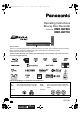


Getting started
VQT2J65
7
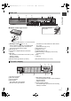
1 Standby/on switch (Í/I) (> 11, 14)
Press to switch the unit from on to standby mode
or vice versa. In standby mode, the unit is still
consuming a small amount of power.
2 Disc tray (> 14)
3 Connection for digital video (DV) camcorder
(> 62)
4 Blue LED
≥It is possible to set the LED to turn on/off. (> 82)
5 Display (> below)
6 Recording indicator
7 Remote control signal sensor (> above)
8 Connection for VCR, Panasonic’s video camera,
etc. (> 62)
9 Open/close disc tray (> 14)
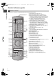
: SD card slot (> 14)
; USB port (> 14)
< Channel select (> 16)
= Start recording (> 21)/Specify a time to stop
recording (> 21)
> Stop
? Start play
Rear panel terminals (> 8, 9, 10, 89)
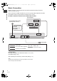
1 SD card slot indicator
2 EXT LINK indicator
3 Copying indicator
4 Disc indicator
5 Drive (HDD, BD or SD) indicator
6 Remote control signal indicator
7 Main display section indicator
Current time/playback counter, various messages
8 Playback indicator
9 USB port indicator
: Timer recording indicator
This indicator lights up when the timer recording
standby is activated.
Main unit
AV3 IN
30
30
20
20
Pull to flip down the
front panel.
Distance: Within approx. 7 m in front of the unit
∫ Remote Control signal sensor
The unit’s display
PLAY
COPYEXT-L
SD USB
HDDSD
BD
DMRBW880&780EB-VQT2J65_eng.book 7 ページ 2010年4月8日 木曜日 午後3時59分