
Operating Instructions EB Model Quick Start Guide


Y
PB
PR
OPTICAL
COMPONENT
VIDEO OUT
(PROGRESSIVE/
INTERLACE)
DIGITAL AUDIO OUT
(PCM/BITSTREAM)
S VIDEO OUT
S VIDEO
AV4 IN
AV4 IN
OUT
AUDIO
R
R
L L
VIDEO
AC IN
AV1 (TV)
AV2 (EXT)
RF OUT
RF IN
- 2 -
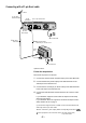
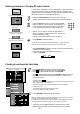
Connecting with a 21-pin Scart cable
1
Aerial
RF IN
Aerial input
RF OUT
Aerial output
AC mains lead
AV1 21-pin Scart socket
RF cable /
Aerial cable
erialA
input
AC mains lead
21-pin Scart cable
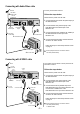
Necessary for TV with Q Link
4
4
TV
VA
1
S
3
S
2
DVD Recorder
AC IN~
S
=Extra equipment for the connection shown: RF cable (Aerial cable)
21-pin Scart cable
If your television supports Q-Link or RGB, connect it to the DVD Recorder
with a fully wired 21-pin Scart cable.
If your television supports Q-Link follow the steps for Auto-Setup
with Q-Link on page 4
If your television does not support Q-Link follow the steps for Auto-
Setup without Q-Link on page 4
.
.
Follow the steps below.
Disconnect the power from all units.
1 Connect the aerial to the RF IN (Aerial input) of the DVD Recorder.
2 Connect the RF OUT (Aerial output) of the DVD Recorder to the
Aerial input of the television set.
3 Connect the AV1 socket (21-pin Scart socket) of the DVD Recorder
to the Scart input of the television set.
4 Connect the DVD Recorder and the television set to the AC mains
socket.
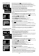
RF cable /
Aerial cable
77
Optimal connection.
SETUP - Connection - [AV1 Output]. Please see Operating Instructions.