
Operating Instructions

7
RQT9118
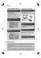
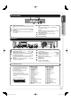
The Unit’s Display
1234
567
1
Digital broadcast indicator
Lights while the unit is receiving digital broadcast or TV Guide
data.
2
Linked timer recordings with external equipment
indicator .................................................... (➔ 25
)
3
Disc indicator
This indicator lights up when a disc that is supported by this
unit is inserted.
4
Timer recording indicator .......................... (➔ 19
)
On:
When a timer recording programme is registered and a
recordable disc is inserted.
Flashes:
The timer recording indicator flashes when the unit cannot go to
timer recording standby (e.g. there is no disc, etc.).
5
Main display section
Current time/playback counter, various messages.
6
Playback indicator
7
Recording indicator
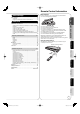
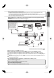
Rear Panel
AV1
(
TV
)
COMPONENT
VIDEO OUT
AV O U T
AV2
(
EXT
)
VH6HA001038 R August 2006
Ser. No.
465897
bn
RF
OUT
RF
IN
DIGITAL AUDIO OUT
(
PCM/BITSTREAM
)
OPTICAL
312
COMPONENT
VIDEO OUT
AV O U T
bk bmbl
DMR-EZ28EB-S
PR000001014
SER NO.
1
Aerial input terminal .......................... (➔ 8, 9, 58)
2
Aerial output terminal ....................... (➔ 8, 9, 58)
3
Digital audio output terminal ..................... (➔ 60)
4
COMPONENT VIDEO OUT (PROGRESSIVE/
INTERLACE) terminals ............................ (➔ 59)
Y = Luminance signal (brightness), P
B
= Chrominance
signal (colour difference), P
R
= Chrominance signal (colour
difference)
5
AV2 (EXT) 21-pin Scart terminal .......... (➔ 9, 58)
Connection of an external unit
6
AV1 (TV) 21-pin Scart terminal ........ (➔ 8, 9, 58)
TV set connection
7
AUDIO output terminals ...................... (➔ 59, 60)
8
Video output terminal................................ (➔ 59)
9
S VIDEO output terminal .......................... (➔ 59)
bk
HDMI AV OUT terminal ...................... (➔ 10, 60)
Digital audio and video output terminal
bl
Cooling fan
bm
Serial number
bn
AC IN~ = Power supply
Connection for the AC mains lead
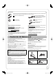
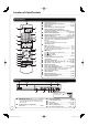
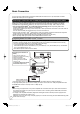
21-pin Scart terminal
19
20
21
1
3
5
7
9
11
13
15 17
2
4
6
8
10 12 14 16 18
The 21-pin Scart terminal transmits both input
and output signals for picture and sound.
TVs equipped with the same type of terminal
can be connected here.
This type of terminal is also called Peritel,
Euro Connector and Euro AV.
AV1 Scart terminal (TV)
V1 Scart terminal (TV)
AV2 Scart terminal (EXT)
V2 Scart terminal (EXT)
1 Audio output CH2 (R) 1 Audio output CH2 (R)
2 Audio input CH2 (R) 2 Audio input CH2 (R)
3 Audio output CH1 (L) 3 Audio output CH1 (L)
4 Audio ground 4 Audio ground
5 Blue ground 5 Blue ground
6 Audio input CH1 (L) 6 Audio input CH1 (L)
7 Blue output 7 Blue input
8 Switching voltage output 8 Switching voltage input
9 Green ground 9 Green ground
10 Q Link control signal 10 Reserved
11 Green output 11 Green input
12 Reserved 12 Reserved
13 Red ground 13 Red ground
14 Blanking ground 14 Blanking ground
15 Red output / chrominance output 15 Red input / chrominance input
16 Blanking output 16 Blanking input
17 Video output ground 17 Video output ground
18 Video input ground 18 Video input ground
19 Video output / luminance output 19 Video output
20 Video input 20 Video input / luminance input
21 Ground 21 Ground
• When the unit is connected to a
Q Link-compatible TV with a fully wired 21-pin
Scart cable, you can use convenient functions
of Q Link.
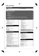
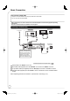
Quick Start Guide
STEP 1
DMR-EZ28-EB _RQT9118-B.indb 7DMR-EZ28-EB _RQT9118-B.indb 7 2008/04/04 10:31:452008/04/04 10:31:45