Digital Video Cassette Recorder AJ- P Operating Instructions ON OFF EJECT POWER DIGIT INPUT LINE S-VIDEO AL VIDE O CASS ETTE SELECT Digital Video Cassett e Record er OPTION AU DIO REC LEV ELE CH1 BEGIN END dB AUDIO OUT SELECT CH1 CH2 CH2 - CTL TC UB CH3 CH4 REW MODE LOCAL MENU REMOTE REC INH REMOTE -30 -25 -20 -16 WIDE -12 -8 DV -4 0 STOP DOWN FF MENU UP SERVO HOURS MINUTE S SEC ONDS FRAMES PLAY | PAUSE/ STTIL DATA + REC RESET COUNTE R SET REMO TE Printed in Japan VQ
IMPORTANT “Unauthorized recording of copyrighted television programs, video tapes and other materials may infringe the right of copyright owners and be contrary to copyright laws.” CAUTION: CAUTION TO REDUCE THE RISK OF FIRE OR SHOCK HAZARD AND ANNOYING INTERFERENCE, USE THE RECOMMENDED ACCESSORIES ONLY. RISK OF ELECTRIC SHOCK DO NOT OPEN CAUTION: TO REDUCE THE RISK OF ELECTRIC SHOCK, DO NOT REMOVE COVER (OR BACK). NO USER SERVICEABLE PARTS INSIDE. REFER TO SERVICING TO QUALIFIED SERVICE PERSONNEL.
Contents Introduction . . . . . . . . . . . . . . . . . . . . . . . 4 Setup Menus . . . . . . . . . . . . . . . . . . . . . . 27 Features . . . . . . . . . . . . . . . . . . . . . . . . . . 4 SYSTEM menu . . . . . . . . . . . . . . . . . . . . . . . . . . 27 BASIC menu . . . . . . . . . . . . . . . . . . . . . . . . . . . . 28 OPERATION menu . . . . . . . . . . . . . . . . . . . . . . . 29 INTERFACE menu . . . . . . . . . . . . . . . . . . . . . . . 30 TAPE PROTECT menu . . . . . . . . . . . . . . . . .
Introduction The AJ-D250 is a digital VTR which uses 1/4˝ wide tapes. The incorporation of digital compression technology ensures that the deterioration in picture and sound quality suffered during dubbing will be much less than with conventional analog systems. The model has a compact and lightweight design, enabling it to be readily carried about or easily installed in a rack.
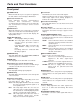
Parts and Their Functions Front panel Counter display 4 5 6 7 8 9 SERVO REC INH REMOTE WIDE DV dB - -30 -25 -20 -16 -12 -8 -4 CTL TC UB 0 CH 1 CH 2 HOURS ; : MINUTES < SECONDS FRAMES = 1 2 3 ON > EJECT OFF MENU POWER LOCAL DIGITAL VIDEO CASSETTE REMOTE Digital Video Cassette Recorder INPUT SELECT LINE S-VIDEO OPTION AUDIO BEGIN END REC LEVEL CH 1 AUDIO OUT SELECT CH 2 RESET COUNTER CH 3 CH 4 REW STOP MODE DOWN FF MENU UP PLAY - PAUSE/STILL DATA + REC SET REMOTE
Parts and Their Functions Front panel 1 POWER switch When the ON side is pressed, power is supplied to the unit, and the counter display is illuminated. ; Level meter This indicates the levels of the audio signals. During recording or E-E selection, it indicates the audio input signal levels; during playback, it indicates the audio output signal levels.
Parts and Their Functions D Headphones jack When headphones are connected to this jack, they can be used to monitor the sound being recorded or played back. M REMOTE connector When the remote control (AG-A11) is plugged into this connector, the unit can be operated at a distance using the controls on the remote control instead of the unit’s function buttons. Keep the LOCAL/MENU/REMOTE switch at the REMOTE position. E Volume control This is used to adjust the volume to the headphones.
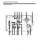
Parts and Their Functions Connector panel 5 6 INPUT S-VIDEO VIDEO 7 8 3 4 REF VIDEO AUDIO CH2 CH1 OUTPUT RS232C S-VIDEO AUDIO 1 CH2 CH1 VIDEO VIDEO MONIT AUDIO 2 CH2 CH1 AC IN SIGNAL GND > 9 < : = ; 8 2 1
Parts and Their Functions Connector panel 1 AC IN socket Plug one end of the unit’s power cord into this power socket. > RS-232C connector Editing operations can be conducted speedily and efficiently by connecting the RS-232C remote control (AJ-A250 - available as an optional accessory) to this connector. Various operations can be performed from a computer by using the RS-232C cable which is available as an optional accessory.
Tapes Tape Description Consumer-use cassettes (S cassette) These tapes are designed to be used exclusively with consumer-use camera recorders. They can be used only for playback on this unit and only with the cassette adapter (optional accessory). Long-playing tapes (80 min. in standard mode, 120 min. in LP mode) cannot be used with this unit. It is recommended that Panasonic brand consumer-use DV tapes be used.
Operation Turning on the power/inserting a cassette Before proceeding to operate the unit, make sure that the unit has been connected properly. 1 2 3 Turn on the unit’s power. Insert the cassette tape. Insert it at the prescribed position without forcing it in any way. Check that the STOP lamp is lighted. When the tape is inserted, the cylinder starts rotating automatically, the tape is loaded, and the STOP mode is established.
Operation STOP mode 1 When the STOP button is pressed, the STOP mode is established. The STOP lamp lights, and the tape stops traveling. O In order to protect the tape, the tape protection mode will be established when the time selected for the “STILL TIMER” setup menu item setting has elapsed. (See page 31) When the STOP, REW, FF or PLAY button is pressed, the corresponding mode will be established.
Operation Recording 1 Set the accidental erasure prevention tab on the cassette tape to “recording,” and insert the tape. 2 Press the STOP button to set the unit to the STOP mode. 3 Check that the REC INH lamp has gone off. 4 Selecting the video and audio input signals and adjusting the audio levels 5 6 4-1 Selecting the video and audio input signals 1 Connect the signals which are to be recorded. 2 Select the input signals using the INPUT SELECT switch on the front panel.
Operation Pause/record (frame-to-frame continuity) 1 2 3 Press the PAUSE/STILL button while the cassette tape is playing. When ON has been selected as the AUTO BACK setup menu item setting, the tape will be rewound for about 2 seconds starting from the position where the PAUSE/STILL was pressed. (See page 29) Press the REC button to set the unit to the REC PAUSE mode. The monitor display now switches to the E-E screen. Press the PAUSE/STILL button to commence recording.
Operation Frame by frame advance When the FF or REW button is pressed during still picture playback, the tape will be advanced forward or backward one frame at a time. O No sound will be heard during frame by frame advance. Audio switching The AUDIO OUT SELECT button is used to switch to the desired sound. By pressing this button, the audio output is switched to the modes in the sequence shown below.
Operation Repeat playback Setting the BEGIN and END points [Menu mode] 1 2 3 4 5 6 7 Set the unit to the menu mode (by setting the LOCAL/MENU/REMOTE switch to the MENU position). Select the “BGN PRESET” or “END PRESET” setup menu item, and press the DATA+ button (PAUSE/STILL button) or DATA– button (PLAY button). (See page 29) It is possible to select whether the BEGIN or END point is to be set or not by operating the DATA+ or DATA– button. Select TC or CTL using the COUNTER button.
Operation Setting the BEGIN and END points [Front panel] 1 2 Set the unit to the local mode (by setting the LOCAL/MENU/REMOTE switch to the LOCAL position). When the BEGIN or END button on the front panel is pressed, the current position is set as the BEGIN or END point. Displaying the BEGIN and END points 1 2 Set the unit to the remote mode (by setting the LOCAL/MENU/REMOTE switch to the REMOTE position).
Time Codes and User’s Bit Time codes Time codes are used when recording time code signals generated by the time code generator on the tape, reading out their values with the time code reader, and displaying the absolute positions of the tape in increments of hours, minutes, seconds and frames. The time codes are written in the sub-code area (data area) of the helical track. For this reason, they can be read at any playback speed from the stop mode to slow-motion playback or highspeed playback.
Time Codes and User’s Bit Setting the time code 1 2 3 4 Set the unit to the menu mode (by setting the LOCAL/MENU/REMOTE switch to the MENU position). Select the “TC PRESET” setup menu item, and press the DATA+ button (PAUSE/STILL button) or DATA– button (PLAY button). (See page 32) Select the digit to be changed (blinking display) using the UP button (FF button) or DOWN button (STOP button).
Time Codes and User’s Bit Playing back the time code/user’s bit 1 2 Set the unit to the STOP mode. Set to TC or UB using the COUNTER button. TC: The time code appears on the display. UB: The user’s bit appears on the display. O Interpolation is provided by the CTL signal if the time code cannot be read. 3 Press the PLAY button. Playback is commenced, and the time code appears on the display.
Superimposed Screens When the unit’s MONITOR OUT connector has been connected to a TV monitor, the control signals, time codes, etc. are displayed on the TV monitor screen as abbreviations. The display can be switched ON or OFF using the setup menu item No. 000 setting. (See page 28) Display position The position where the superimposed display appears can be changed using setup menu item No.002 “CHARA H-POS” and No.003 (CHARA V-POS).
Superimpose Screens Operation mode The value to be displayed can be selected using setup menu item No.001 “DISPLAY SEL”. (See page 28) TIME: Counter value T&STA: Counter value and VTR operation mode T&R: Counter value and remaining tape amount T&S&R: Counter value, VTR operation mode and remaining tape amount One of the following errors may be displayed on the third line (remaining tape amount line) in the T&S&R mode.
Setup (Initial Settings) The unit’s main settings can be performed and checked using the on-screen menus which appear on the video monitor connected to the unit. It is also possible to perform and check the settings using the item numbers and setting numbers which appear on the front panel’s display. One user setting memory set is provided with the unit to enable the desired settings to be stored in the memory ahead of time for use.
Setup (Initial Settings) 3 3 Press the MENU-UP button or MENU-DOWN button to position the cursor at LOAD, and press the SET button. The unit is set to the LOAD mode, and the LOAD screen appears on the video monitor. Press the RESET button. The unit is set to the default setting mode, and the default setting screen appears on the video monitor.
Setup (Initial Settings) How to load the user default settings How to initiate protect mode 1 By setting the unit to the menu protect mode, the opening of the setup menus can be disabled even if the front panel’s LOCAL/MENU/REMOTE switch is set to the MENU position. 2 Set the LOCAL/MENU/REMOTE switch to the MENU position. The unit is now set to the menu setting mode, and the menu screen appears on the video monitor. Press the RESET button.
Setup (Initial Settings) 5 How to display the DIAG menu Set the LOCAL/MENU/REMOTE switch to the LOCAL or REMOTE position. The unit is now set to the menu protect mode. When the LOCAL/MENU/REMOTE switch is set to the MENU position, “MENU PROTECTED” appears on the video monitor screen instead of the menu setting mode being established. This unit incorporates a function for displaying the HOURS METER and software program version on the video monitor.
Setup Menus SYSTEM menu Item No. Superimposed display Setting No. Description of setting Superimposed display 00 SYSTEM H 0000 128 For adjusting the horizontal phase. This item enables the phase to be varied by up to ±1.5 µ. 0255 127 01 SC COARSE 0000 0001 0002 0003 0 For coarsely adjusting the subcarrier phase. 90 This item enables the phase to be varied by selecting one of 4 positions at 180 90-degree increments. 270 02 SC FINE 0000 0255 128 For finely adjusting the subcarrier phase.
Setup Menus BASIC menu Item No. 000 Superimposed display Setting No. SUPER 0000 0001 001 003 004 For setting whether to show the superimposed display from the MONITOR OUT connector. OFF 0: The superimposed display is not shown. ON 1: The superimposed displayed is shown. DISPLAY SEL 0000 0001 0002 0003 002 Description of setting Superimposed display CHARA H-POS CHARA V-POS TIME T&STA T&R T&S&R For setting what is to be shown by the superimposed display from the MONITOR OUT connector.
Setup Menus OPERATION menu Item No. 100 Superimposed display Setting No. LOCAL ENABLE 0000 0001 101 TAPE TIMER 0000 0001 102 S/F/R EE SEL 0000 0001 103 WIDE MODE 0000 0001 0002 104 105 AUTO BACK 0000 0001 107 108 109 FORMAT SEL For selecting the WIDE mode. AUTO 0: The mode is detected automatically. WIDE 1: The mode is forcibly treated as WIDE. NORMAL 2: The mode is forcibly treated as NORMAL.
Setup Menus INTERFACE menu Item No. Superimposed display Setting No. Description of setting Superimposed display 200 BAUD RATE 0000 0001 0002 0003 0004 201 DATA LENGTH 0000 0001 8BIT For setting the RS-232C data length. 7BIT 202 STOP BIT 0000 0001 1BIT For setting the RS-232C stop bit. 2BIT 203 PARITY 0000 0001 0002 204 ACK RETURN 0000 0001 205 232C ID SEL 0000 0001 1200 For setting the RS-232C transmission speed (baud rate).
Setup Menus TAPE PROTECT menu Item No. Superimposed display 400 STILL TIMER 401 SRC PROTECT Setting No. 0000 0001 0002 0003 0004 0005 0000 0001 402 403 DRUM STDBY Description of setting Superimposed display 0.5s 5s 10s 30s 1min 2min For selecting the time taken for the tape protection mode to be established when the unit has been left standing in the STOP, PLAY, PAUSE or STILL mode.
Setup Menus TIME CODE menu Item No. 500 501 502 503 504 Superimposed display VITC POS-1 VITC POS-2 Setting No. 0000 0001 10L For setting the position where the VITC signal is to be inserted. 11L (The same line as the one set for the VITC POS-2 item cannot be selected.) 0006 16L 0010 20L 0000 0001 10L For setting the position where the VITC signal is to be inserted. 11L (The same line as the one set for the VITC POS-1 item cannot be selected.
Setup Menus VIDEO menu Item No. 600 Superimposed display Setting No. VIDEO MODE 0000 0001 601 V-MUTE SEL 0000 0001 602 603 604 605 CC (F1) BLANK 607 608 For setting the recording and playback of the video signals. B/W 0: When monochrome signals are used COLOR 1: When color signals are used OSet this item to the B/W mode when monochrome signals are to be recorded or played back. Set the item to the COLOR mode with regular color signals.
Setup Menus AUDIO menu Item No. 700 701 702 703 704 705 Superimposed display Setting No. AUDIO EDIT IN Description of setting Superimposed display 0000 0001 For selecting the joining method at the IN point during digital audio editing. CUT 0: Cutting FADE 1: Fading 0000 0001 For selecting the joining method at the OUT point during digital audio editing.
Editing Editing with the RS-232C remote control Using the RS-232C remote control (AJ-A250), which is available as an optional accessory, two units—a player VTR and a recorder VTR—can be controlled directly from the controller to enable speedier and more efficient assemble editing, insert editing and other editing jobs. Preparation: O As shown in the figure below, connect the player VTR and recorder VTR to the RS-232C remote control.
Audio editing functions The information (setup menu item No. 700, 701) concerning the selection of the joining method used at the edit points is recorded during digital audio editing, and this information is detected during playback so that the edit points can be processed automatically. This applies only when AUTO has been selected as the playback fade selection (setup menu item No.702) setting. Cutting When CUT has been selected as the joining method at the edit points. (setup menu item No.
First Edit Function (Preparing the editing tape) The CTL (control) signal must be recorded ahead of time onto the editing tape. The method used to record it differs depending on whether assemble editing or insert editing is to be performed. First edit for assemble editing In the case of a tape for assemble editing, the CTL signal is recorded at the beginning of where the recording is to be commenced. Position where CTL signal recording starts 3 sec. Direction of tape travel CTL signal recording –23 sec.
RS-232C The following functions can be controlled using the RS-232C interface. $ Basic operations EJECT STOP PLAY REC/PLAY FF REW PAUSE COUNTER RESET Example of connections Computer end Frame INSERT SEARCH PAUSE SEARCH SPEED UP SEARCH SPEED DOWN FORWARD/ADVANCE REVERSE/ADVANCE REVERSE/PLAY DIRECT SEARCH $ Status checks The current VTR mode can be checked. 1.
RS-232C 2. Software specifications (2) Sending format (computer (1) External interface specifications $ Data format Communication system Asynchronous system, full duplex Baud rate 1200, 2400, 4800, 9600 or 19200 bps Bit length 8 bits or 7 bits Stop bit 1 bit or 2 bits Parity None, odd or even [STX] [discrimination] [:] 02H XX XX XX 3AH 20H
RS-232C (3) Receiving format (VTR 2) If there were errors in the data or any problems in the VTR, a description of the reason why the data was not received is returned in the following format. computer) The VTR responds to a send command with the format data below. [STX] E R 02H 45H 52H 1. First, the VTR returns the data indicating whether the command from the computer was received properly.
RS-232C (4) Command list $ List of commands The table below lists the send commands and operations for each mode as seen from the computer end. [STX] = HEX code 02H [ETX] = HEX code 03H : = HEX code 3AH The discrimination part and data part represent the ASCII codes which support the corresponding symbols. OAudio control commands Sends data of computer Return data from VTR [STX] AOC:m [ETX] [STX] AOC [ETX] Description of command Sets the audio signal output channel.
RS-232C ODisplay control commands Sends data of computer Return data from VTR [STX] DFC:m [ETX] [STX] DFC [ETX] Description of command Sets the display mode of the display counter. OEdit control commands Sends data of computer Return data from VTR Description of command [STX] EAB:m [ETX] [STX] EAB [ETX] Sets the auto back recording.
RS-232C OOperation control commands Sends data of computer Return data from VTR [STX] OAF [ETX] [STX] OAF [ETX] Advances frames in the forward direction. [STX] OAR [ETX] [STX] OAR [ETX] Advances frames in the reverse direction.
RS-232C OQuery control commands Sends data of computer Return data from VTR Description of command [STX] QAL [ETX] [STX] ALV0 [ETX] Queries the address level. [STX] QAO [ETX] [STX] AOm [ETX] Queries the audio output channels. [STX] QCA [ETX] [STX] CUPdata [ETX] Queries the user’s bit data which was preset in the TCG. [STX] QCB [ETX] [STX] CUSdata [ETX] Queries the user’s bit data of the TCG. [STX] QCC [ETX] [STX] CCPdata [ETX] Queries the counter data (same as QCD).
RS-232C OQuery control commands Sends data of computer Return data from VTR Description of command [STX] QLH:m [ETX] [STX] LHRdata [ETX] [STX] QOT [ETX] [STX] OTEm [ETX] [STX] QOP [ETX] [STX] data [ETX] [STX] QOD:d1d2 [ETX] [STX] OASdata [ETX] Queries the operation modes. [STX] QOS [ETX] [STX] OPSdata [ETX] Queries the operation modes.
RS-232C OSearches control commands Sends data of computer Return data from VTR Description of command [STX] SCP:data [ETX] [STX] SCP [ETX] Searches the counter value and play. [STX] SCS:data [ETX] [STX] SCS [ETX] Searches the counter value and sets to still picture (same as SRS). [STX] SMI:data [ETX] [STX] SMI [ETX] Sets the memory search data. [STX] SMM:m [ETX] [STX] SMM [ETX] Sets the memory mode. [STX] SMP:data [ETX] [STX] SMP [ETX] Specifies the repeat position.
RS-232C $ Audio control commands Sends data of computer Return data from VTR [STX] AOC:m [ETX] Parameters m = 1: CH1 2: CH2 3: CH3 4: CH4 5: CH1 & CH2 6: CH3 & CH4 7: CH1+3 & CH2+4 [STX] AOC [ETX] Description of command Sets the audio signal output channel/s. Playback output is possible for CH3 and CH4 when audio signals for 4 channels have been recorded on a DV format tape. This command is ignored while a search control command is being processed.
RS-232C $ Counter control commands Sends data of computer Return data from VTR Description of command [STX] CLP:data [ETX] Parameters data = ghmmssff g = Blank: With a positive value – sign: With a negative value h = 0 9: Hours mm = 00 59: Minutes ss = 00 59: Seconds ff = 00 29: Frames [STX] CLP [ETX] Presets the designated counter value on the CTL counter. The value will be corrected as follows if the non-drop frame preset value has been set while the drop frame mode is established.
RS-232C $ Counter control commands Sends data of computer Return data from VTR [STX] CTP [ETX] [STX] CTP [ETX] Uses the TCG in the preset mode. The TCG starts counting up in the REC RUN mode upon completion of the settings. This command is ignored while a search control command is being processed, during recording and in the INSERT mode. [STX] CTR [ETX] [STX] CTR [ETX] Uses the TCG in the regeneration mode.
RS-232C $ Edit control commands Sends data of computer Return data from VTR Description of command [STX] EAB:m [ETX] Parameters m = N: AUTO BACK ON F: AUTO BACK OFF [STX] EAB [ETX] Sets whether auto back recording is to be performed to ensure frame to frame continuity. This command is ignored while a search control command is being processed and during auto back.
RS-232C $ Media operation control commands Sends data of computer Return data from VTR Description of command [STX] HRE:m [ETX] Parameters m = S: STOP R: REWIND E: EJECT M: REWIND and EJECT [STX] HRE [ETX] Sets the VTR’s operation mode when the tape end position is reached during recording. This command is ignored while a search control command is being processed.
RS-232C $ Operation control commands Sends data of computer Return data from VTR Description of command [STX] OAF [ETX] [STX] OAF [ETX] Advances the tape frame by frame in the forward direction. [STX] OAR [ETX] [STX] OAR [ETX] Advances the tape frame by frame in the reverse direction. [STX] OBF [ETX] [STX] OBF [ETX] Sets the VTR to the standby OFF mode. This command can be accepted when the VTR is in the STOP mode, PLAY mode or STILL mode.
RS-232C $ Operation control commands Sends data of computer Return data from VTR Description of command [STX] OSD [ETX] [STX] OSD [ETX] Controls the tape playback speed. Set the VTR to the STILL PAUSE mode using the OSL command, and send the OSD command. Each time the OSD command is sent, the playback speed shifts by one setting in the direction of the arrows below. If the lowest playback speed is already set, the speed does not shift any further, and error code ER001 is returned from the VTR.
RS-232C $ Operation control commands Sends data of computer [STX] OSR:n [ETX] Parameters OIn the case of a DVCPRO format tape n = 0: 1: 2: 3: 4: 5: STILL a0.03 a0.1 a0.3 a0.43 a1 6: 7: 8: 9: A: Return data from VTR Description of command [STX] OSR [ETX] Sets the tape playback speed in the reverse direction. [STX] OSU [ETX] Controls the tape playback speed. Set the VTR to the STILL PAUSE mode using the OSL command, and send the OSU command.
RS-232C $ Query control commands Sends data of computer Return data from VTR [STX] QAL [ETX] [STX] ALV0 [ETX] [STX] QAO [ETX] m = 1: 2: 3: 4: 5: 6: 7: Description of command Supports only address level 0 of the MIS standards. [STX] AOm [ETX] CH1 CH2 CH3 CH4 CH1 & CH2 CH3 & CH4 CH1+3 & CH2+4 Queries the audio signal output channel or channels. [STX] QCA [ETX] [STX] CUPdata [ETX] data = U7U6U5U4U7U3U2U1U0 Queries the user’s bit data which was preset in the TCG.
RS-232C $ Query control commands Sends data of computer Return data from VTR Description of command [STX] QCE [ETX] [STX] CTEdata [ETX] data = hhmmssff hh = 00 23: Hours mm = 00 59: Minutes ss = 00 59: Seconds ff = 00 29: Frames Queries the time data which was preset in the TCG. [STX] QCF [ETX] [STX] CDm [ETX] m = N: Drop frame mode F: Non-drop frame mode Queries the drop frame mode.
RS-232C $ Query control commands Sends data of computer Return data from VTR Description of command [STX] QEB [ETX] [STX] EABm [ETX] m = N: AUTO BACK ON F: AUTO BACK OFF Queries the auto back recording setting.
RS-232C $ Query control commands Sends data of computer [STX] QIE [ETX] Return data from VTR Description of command [STX] IEVdata [ETX] Queries the forced E-E output setting. data = m1m2 m1 = 0 F: Designates the data of bit 7 to bit 4. m2 = 0 F: Designates the data of bit 3 to bit 0.
RS-232C $ Query control commands Sends data of computer [STX] QOP [ETX] [STX] QOD:d1d2 [ETX] Parameters d1 = 0 F: Designates the status data number. d2 = 0 F: Designates the number of status data bytes.
RS-232C OBitmap table (A) ADDRESS BIT7 BIT6 BIT5 BIT4 BIT3 BIT2 BIT1 BIT0 AD 0 0 0 CASSETTE OUT RF VIDEO MISSING TAPE TROUBLE HARD ERROR 0 LOCAL or MENU AD 1 STANDBY 0 STOP EJECT REW FF REC PLAY AD 2 SERVO LOCK 0 SHUTTLE 0 0 TAPE DIRECTION STILL CUE UP COMPLETE AD 3 0 0 0 0 0 0 0 0 AD 4 SELECT EE FULL EE 0 EDIT 0 0 0 CUE UP AD 5 0 INSERT 0 VIDEO 0 0 AUDIO CH2 AUDIO CH1 AD 6 0 LAMP STILL LAMP FWD LAMP REW LAMP SPEED3 LAMP SPEED2 LAMP SPEED
RS-232C $ Query control commands Sends data of computer Return data from VTR Description of command [STX] QOS [ETX] [STX] OPSdata [ETX] data = AD0AD1AD2AD3AD4 Refer to the bitmap table (B) for details of AD . Queries the operation modes. The current VTR mode is detected and sent by the bitmap information. The bitmap information is converted into ASCII code and returned by the VTR. [STX] QRA [ETX] [STX] RAm [ETX] m = N: ACK ON F: ACK OFF Queries the ACK (Acknowledge) code response setting.
RS-232C OBitmap table (B) ADDRESS BIT7 BIT6 BIT5 BIT4 BIT3 BIT2 BIT1 BIT0 AD 0 FULL EE SELECT EE 0 0 0 0 TAPE END ( ) TAPE TOP ( ) AD 1 SHORT PLAY 0 STANDBY 0 0 0 0 SERVO LOCK AD 2 REC INHIBIT TAB CASSETTE IN/OUT 0 AD 3 TAPE DIRECTION AD 4 0 0 0 VTR STATUS SHUTTLE SPEED INSERT VIDEO INSERT AUDIO CH1 INSERT AUDIO CH2 0 0 “1” is used as the TAPE END bit and TAPE TOP bit when the tape start or end is detected, and the bits are cleared to “0” when queried by t
RS-232C $ Query control commands Sends data of computer Return data from VTR Description of command [STX] SMPdata [ETX] data = pw:ghmmssff OWhen CTL data is to be used as the reference pw = BP: BEGIN point EP: END point g = Blank: With a positive value – sign: With a negative value h = 0 9: Hours mm = 00 59: Minutes ss = 00 59: Seconds ff = 00 29: Frames OWhen TC data is to be used as the reference pw = BP: BEGIN point EP: END point gh = 00 23: Hours mm = 00 59: Minutes ss = 00 59: Seconds ff = 00 29: Fr
RS-232C $ Communication control commands Sends data of computer Return data from VTR [STX] RAN [ETX] [STX] RAN [ETX] Enables the return of the ACK (Acknowledge) code. This command is ignored while a search control command is being processed. [STX] RAF [ETX] [STX] RAF [ETX] Disables the return of the ACK (Acknowledge) code. This command is ignored while a search control command is being processed. [STX] RCK [ETX] [STX] RCK [ETX] Checks whether communication is established.
RS-232C $ Search control commands Sends data of computer Return data from VTR [STX] SCP:data [ETX] Parameters data = ghmmssff OWhen CTL data is to be used as the reference g = Blank: With a positive value – sign: With a negative value h = 0 9: Hours mm = 00 59: Minutes ss = 00 59: Seconds ff = 00 29: Frames OWhen TC data is to be used as the reference gh = 00 23: Hours mm = 00 59: Minutes ss = 00 59: Seconds ff = 00 29: Frames [STX] SCP [ETX] Description of command Searches the counter value which was d
RS-232C $ Search control commands Sends data of computer Return data from VTR [STX] SMI:data [ETX] Parameters data = wwghmmssff OWhen the counter value is to be stored in the memory ww = LC: CTL data reference SC: TC data reference “ghmmssff” is omitted.
RS-232C $ Search control commands Sends data of computer Return data from VTR Description of command [STX] SMP:data [ETX] Parameters data = pww:ghmmssff OWhen the counter value is to be stored in the memory p = B: BEGIN point E: END point ww = LC: CTL data reference SC: TC data reference “ghmmssff” is omitted.
RS-232C $ Search control commands Sends data of computer Return data from VTR Description of command [STX] SMS [ETX] [STX] SMS [ETX] Searches the counter value at the time when the command stored in the memory was received. The STILL mode is established upon completion of the search. If the designated position is an illegal position (the target position does not exist), error code ER122 will be returned from the VTR which is then set to the STOP mode.
RS-232C $ Search control commands Sends data of computer Return data from VTR [STX] SRS:data [ETX] Parameters data = wghmmssff OWhen CTL data is to be used as the reference w = L: CTL data reference g = Blank: With a positive value – sign: With a negative value h = 0 9: Hours mm = 00 59: Minutes ss = 00 59: Seconds ff = 00 29: Frames OWhen TC data is to be used as the reference w = S: TC data reference gh = 00 23: Hours mm = 00 59: Minutes ss = 00 59: Seconds ff = 00 29: Frames [STX] SRS [ETX] Descripti
RS-232C $ Timer control commands Sends data of computer [STX] TST:data [ETX] Parameters data = mmmm mmmm = 0000: 0.5 sec. 0005: 5 sec. 0010: 10 sec. 0030: 30 sec. 0100: 1 min. 0200: 2 min. Return data from VTR [STX] TST [ETX] Description of command Sets the standby OFF timer. This command is ignored while a search control command is being processed.
RS-232C $ Mode transition table VTR STATUS Return command STOP STANDBY EJECT OFF ± OSP t PLAY REW FF PLAY PAUSE REC REC PAUSE SHORT PLAY AUTO BACK SEARCH ± ± ± ± ± ± ± ± ± ± ± ± ± t t t t ± ± ± ± t t t t ± ± ± ± ± ± ± ± ± ± ± ± ± ± REC PAUSE REC REC PAUSE REC ± ± ± ± ± ± ± t OEJ ± ± OPL ± ± t ORW ± ± t ± OFF ± ± t ± ± OPA ± ± t ± ± ± PLAY ORC ± ± t ± ± ± ± ORP ± ± t ± t t ± ± EIN t t t t t t ±
RS-232C $ Mode transition table VTR STATUS Return command STILL VIDEO INSERT VIDEO INSERT PAUSE AUDIO INSERT AUDIO INSERT PAUSE A/V INSERT A/V INSERT PAUSE FIRST EDIT Processing Search Command (Cue Up, etc.
RS-232C (5) Checkpoints for RS-232C communication $ Send commands and data returned from the VTR 1. If the LOCAL/MENU/REMOTE switch on the front panel is not at the REMOTE position, it is not possible to exercise proper control using the RS-232C interface. If any command except a Q (query) command is sent while this switch is not at the REMOTE position, error code ER001 is returned. 2.
Error Messages When a problem has occurred in the unit, one of the following error messages will appear on the tape counter. Error No. Description Error No. Description E — 51 The FG signal (rotational speed signal) is not output from the capstan motor. E — 52 The capstan motor speed is abnormally high. E — 53 The capstan motor speed is abnormally low. E — 61 The supply (S) reel motor is locked. Appears when there is no head output for one or more seconds (due to clogging, etc.).
Emergency Eject Procedure for removing the tape manually in an emergency Use the procedure below to remove the cassette tape if it can not be removed even when the EJECT button is pressed. OBefore proceeding to eject the tape manually, you must first turn off the power to the unit. 1 Remove the top panel. 4 Use the Phillips head screwdriver to push in and turn the red plastic screw part counterclockwise once more.
Video Head Cleaning This unit is equipped with an auto head cleaning function which automatically reduces the amount of dirt on the video heads. However, in order to maximize the unit’s reliability, it is recommended that the video heads be cleaned as and when appropriate. For further details on how to actually clean the heads, consult with one of our service companies or with your dealer.
Specifications [GENERAL] [VIDEO] $ Digital video Supply voltage: 120 V AC, 50 – 60 Hz Power consumption: 56 W Sampling frequency: Y: 13.5 MHz, PB/PR: 3.375 MHz Quantizing: 8 bits Error correction: Reed-Solomon product code Ambient operating temperature: 41°F to 104°F (5°C to 40°C) Ambient operating humidity: 35% to 80% (no condensation) Weight: 14.3 lb (6.
Specifications [AUDIO] $ Digital audio Sampling frequency: 48 kHz Quantizing: 16 bits Frequency response: 20 Hz to 20 kHz (0 +1.0 dB, –2.0 dB) Dynamic range: More than 85 dB (1 kHz, emphasis OFF, “A” weighted) Distortion: Less than 0.
PANASONIC BROADCAST & DIGITAL SYSTEMS COMPANY DIVISION OF MATSUSHITA ELECTRIC CORPORATION OF AMERICA Executive Office: 3330 Cahuenga Blvd W.