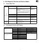
ORDER NO.ODSD000506C3 DVD Player DVD-RV60 Area PM.........................South America. Specifications OGeneral Output terminal: Power requirements: AC 110-240 V, 50/60 Hz Power consumption: 18 W (approx. 4.0 W in STANDBY mode) Dimensions: 430 (W)×271 (D)×82 (H) mm OAudio output Output level: 2.9 kg Signal system: NTSC Operating temperature range: +5 to +35°C Operating humidity range: 5-90 % RH (no condensation) Region number: Region NO.
DVD-RV60 CONTENTS Page 1 SAFETY PRECAUTIONS 1.1. GENERAL GUIDELINES Page 4 11.6. Disassembling the Stepping Motor Unit 20 4 11.7. Disassembling the Optical Pickup Unit 20 11.8. Disassembling the Nut Unit 21 11.9. Disassembling the Sub-Shaft Preload Spring 21 2 PREVENTION OF ELECTRO STATIC DISCHARGE (ESD) TO ELECTROSTATICALLY SENSITIVE (ES) DEVICES 4 3 PRECAUTION OF LASER DIODE 5 11.10. Assembling the Optical Pickup 21 4 HANDLING PRECAUTIONS FOR TRAVERSE DECK 5 11.11.
DVD-RV60 16.11. AUDIO OUT SECTION (MOTHER P.C.B. (2/3)) SCHEMATIC DIAGRAM 17.6. FRONT SWITCH P.C.B. AND POWER SWITCH P.C.B. 58 18 EXPLODED VIEWS 49 16.12. OPERATION SECTION (MOTHER P.C.B. (3/3)) SCHEMATIC DIAGRAM 50 16.13. FRONT SWITCH AND POWER SWITCH SCHEMATIC DIAGRAM 17 PRINTED CIRCUIT BOARD DIAGRAM 51 18.1. Casing Parts & Mechanism Section Exploded View 59 18.2. Loading Mechanism Section Exploded View 60 18.3. Traverse Section Exploded View 61 18.4.
DVD-RV60 1 SAFETY PRECAUTIONS 1.1. GENERAL GUIDELINES 1. When servicing, observe the original lead dress. If a short circuit is found, replace all parts which have been overheated or damaged by the short circuit. 2. After servicing, see to it that all the protective devices such as insulation barriers, insulation papers shields are properly installed. 3. After servicing, make the following leakage current checks to prevent the customer from being exposed to shock hazards. 1.1.1.
DVD-RV60 Caution Be sure no power is applied to the chassis or circuit, and observe all other safety precautions. 8. Minimize bodily motions when handling unpackaged replacement ES devices. (Otherwise hamless motion such as the brushing together of your clothes fabric or the lifting of your foot from a carpeted floor can generate static electricity (ESD) sufficient to damage an ES device). 3 PRECAUTION OF LASER DIODE Caution This unit utilizes a class I laser.
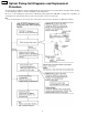
DVD-RV60 5 Optical Pickup Self-Diagnosis and Replacement Procedure The optical pickup self-diagnosis function and tilt adjustment check function have been newly added to this player. When repairing, use the following procedure for effective Self-diagnosis and tilt adjustment. Be sure to use the self-diagnosis function before replacing the optical pickup when "NO DISC" is displayed. As a guideline, you should replace the optical pickup when the value of the laser drive current is more than 55.
DVD-RV60 6 Self-Diagnosis Function and Service Modes 6.1. Service Mode Table The service modes can be activated by pressing various button combinations on the player and remote control unit. Player buttons Remote control unit buttons 0 5 PAUSE + OPEN/CLOSE 6 7 9 DISPLAY PAUSE PAUSE SKIP/SEARCH<< OPEN/CLOSE 6.2. Application Displaying the UHF display F_ _ _ Note Refer to section 6.2, SelfDiagnosis Function (UHF Display). Refer to section 11.12, Optical Pickup Tilt Adjustment.
DVD-RV60 6.3. Examples of Repairs Using Error Codes Refer to this section when carrying out repairs. Error display F0** F103 F4FF F500 F501 F502 F504 F505 F506 F600 F601 F602 F603 F610 F611 F612 F620 F621 F700 F701 F702 F880 F890 F891 F8A0 F893 F894 6.4.
DVD-RV60 7 Service Tools and Equipment 7.1. Service Tools and Equipment Table Application General Tilt adjustment Inspection Others Confirmation Electrical adjustment General Static electricity countermeasures 7.2. Name DVD test disc Hex wrench Adjustment table Extension cable (power supply P.C.B. to mother P.C.B.) Extension cable (mechanism loading P.C.B. to mother P.C.B.) Extension cables (module P.C.B. to mother P.C.B.
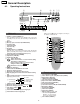
DVD-RV60 8 General Description 8.1. Operating Instructions 1 2 3 4 56 ∫? ; 1 OPEN/CLOSE < V.S.S. POWER CINEMA 6 Í? STANDBY : 6 9 Í/I 7 A =>?@ DVD 8 9: B ANGLE PROG. CD E ; < 96kHz 24bit F GH Buttons such as 1 function in exactly the same way as the buttons on the main unit. Main unit 1 Standby/on switch (POWER, Í/I) Press to switch the unit from on to standby mode or vice versa. In standby mode, the unit is still consuming a small amount of power.
DVD-RV60 9 Assembling and Disassembling the Casing and Checking P.C.B.s 9.1. Disassembly Procedure When servicing the unit, use the following procedure to disassemble the casing and inside parts for internal inspection.
DVD-RV60 9.2. Casing Parts and P.C.B. Positions 9.3. Service Positions Note To inspect the loading base unit, position the left side upward (as viewed from the front).
DVD-RV60 9.4. Disassembling the Top Cover 9.6. 1. Remove the 4 screws. Disassembling the Front Panel 1. Release the 3 tabs on the bottom. 2. Release the 2 tabs on the left and right. 2. Remove the 3 screws. 3. Release the 2 tabs. 4. Disconnect the 2 flexible cables. 9.5. Disassembling the Tray 1. Turn the lever clockwise. 2. Move the tray in the direction of the arrow until it locks. 3. Release the tab locks on the left and right, then pull out the tray.
DVD-RV60 9.7. Disassembling the Loading Base Unit 2. Connect the module P.C.B. to the mother P.C.B. with the extension cables for inspection. 1. Remove the 4 screws. · Extension cable: JGS0098 2. Pull out the loading base unit vertically. · Extension cable: JGS0116 Note Mother P.C.B. Module P.C.B. There is a danger of damaging the connectors. PP4201-PS4201 PP3201-PS3201 3. Connect the mechanism loading P.C.B. to the mother P.C.B.with the extension cable: for inspection.
DVD-RV60 9.10. Checking the Power Supply P.C.B. 9.11. Checking the Mother P.C.B. 1. Remove the 4 screws. 2. Release the tab. 1. Remove the 3 screws. 2. Carefully pull out the power supply P.C.B. Note 3. Check by connecting the module P.C.B. and the mother P.C.B. with the extension cables. There is a danger of damaging the connectors. · Extension cable: JGS0116 3. Connect the power supply P.C.B. and the mother P.C.B. with the extension cable for inspection.
DVD-RV60 9.12. Checking the Front Switch P.C.B. 1. Remove the 3 screws. 9.13. Checking the Power Switch P.C.B. 1. Remove the 2 screws.
DVD-RV60 10 Service Precautions 10.1. Initializing the DVD Player Initialize the DVD player whenever you replace a microprocessor, microprocessor peripheral parts, module P.C.B. or mother P.C.B. 10.1.1. Precautions The customer settings will return to factory preset settings when the player is initialized. Make a note of the settings and reset them after initializing. · When resetting, see the Initial Settings in the Operating Instructions. 10.1.2.
DVD-RV60 11 Assembling and Disassembling the Optical Pickup (Mechanical Parts) The optical pickup can be damaged by static electricity from your body. Be sure to take static electricity countermeasures when working around the optical pickup. 11.1. Handling the Optical Pickup The optical pickup can be damaged by static electricity from your body. Be sure to take static electricity countermeasures when working around the optical pickup. 1. The optical pickup is an extremely high-precision mechanism.
DVD-RV60 2. Release the 3 tabs on the clamper. 11.3. Disassembling the Clamp Base Unit 1. Remove the 2 screws. 11.4. Disassembling the Clamper Weight, Clamper Yoke, Magnet and Clamper 11.5. Disassembling the Traverse Unit 1. Release the tab, and pull out the clamper. 1. Remove the 3 screws. Note Be sure to take static electricitiy countermeasures befer disconnecting the flexible cable.(Refer to section 4, HANDLING PRECAUTIONS FOR TRAVERSE DECK.
DVD-RV60 2. Disconnect the 2 flexible cables. 11.7. Disassembling the Optical Pickup Unit 1. Remove the screw. 2. Release the tab, then remove spring holder 1. Note Be sure not to lose the spring. 3. Remove the guide shaft. Note Be sure to adjust the optical pickup tilt after replacing the optical pickup. (Refer to section 11.12, Opitcal Pickup Tilt Adjustment.) 11.6. Disassembling the Stepping Motor Unit 1. Disconnect the flexible cable. 2. Remove the 2 screws.
DVD-RV60 11.8. Disassembling the Nut Unit 11.10. Assembling the Optical Pickup 1. Remove the screw. 1. Install the optical pickup. Notes Note · The nut unit is not part of the optical pickup. Before replacing the optical pickup, remove the nut unit for use with the new optical pickup. Take care not ot attach the tilt spring and guide shaft in the wrong order. · After installation, use screw lock to lock the screw in position.
DVD-RV60 3. Remove the solder from the pickup FPC´s soldered shortcircuit. 11.11. Disassembling the Spindle Motor Unit 1. Remove the three screws. Note Be sure to adjust the optical pickup tilt after replacing the spindle motor unit. 4. Adjust the optical pickup tilt after removing the solder. (Refer to section 11.12, Optical Pickup Tilt Adjustment.
DVD-RV60 11.12.
DVD-RV60 Notes · Adjustment is generally unnecessary after replacing other parts of the traverse unit. However, adjust if there is a noticeable degradation in picture quality. · Optical adjutments cannnot be made inside the optical pickup. · Adjustment is generally unnecessary after replacing the traverse unit.
DVD-RV60 11.13. Disassembling the Intermediate Chassis 11.15. Disassembling the Pulley Gear and Deceleration Gear 1. Push the stopper downward, then rotate it until it contacts the Vertical cam. 1. Remove the screw. 2. Release the 2 tabs. 3. Remove the belt. 2. Remove the pulley gear. 4. Remove the deceleration gear. 11.14. Disassembling the Vertical cam and Drive gear 1. Rotate the Vertical cam until it reaches the contact position. 2. Lift the Vertical cam straight upward to pull it out. 11.16.
DVD-RV60 12 Electrical Adjustment 12.1. Video Output (Luminance Signal) Adjustment Do this adjustment after replacing a P.C.B. Measurement point Video output terminal Adjustment point VR3501 (mother P.C.B.) Mode Disc Color bar 75% DVDT-S15 PLAY (Title 46):DVDT-S15 or PLAY (Title 12):DVDT-S01 DVDT-S01 Adjustment value 1000mVp-p±20mV Measuring equipment, tools Screwdriver, Oscilloscope 200mV/div, 10µsec/div Purpose: To maintain video signal output compatibility. 1.
DVD-RV60 12.3. Video Component Signal (CB) Output Adjustment Do this adjustment after replacing a P.C.B. Measurement point Video output terminal (Y) (CB) Output terminal Adjustment point VR3201 (module P.C.B.) Mode Disc Color bar 75% DVDT-S15 PLAY (Title 46):DVDT-S15 or PLAY (Title 12):DVDT-S01 DVDT-S01 Adjustment value 486mVp-p±10mV Measuring equipment, tools Screwdriver, Oscilloscope 100mV/div, 10µsec/div Purpose: To maintain video signal output compatibility. 1.
DVD-RV60 13 Abbreviations INITIAL/LOGO A A0~UP ACLK AD0~UP ADATA ALE AMUTE AREQ ARF ASI ASO ASYNC B BCK BCKIN BDO BLKCK BOTTOM BYP BYTCK C CAV CBDO CD CDSCK CDSRDATA CDRF CDV CHNDATA CKSL CLV COFTR CPA CPCS CPDT CPUADR CPUADT CPUIRQ CPRD CPWR CS CSYNCIN CSYNCOUT D DACCK DEEMP DEMPH DIG0~UP DIN DMSRCK DMUTE DO DOUT0~UP DRF DRPOUT DREQ DRESP DSC DSLF DVD ABBREVIATIONS ADDRESS AUDIO CLOCK ADDRESS BUS AUDIO PES PACKET DATA ADDRESS LATCH ENABLE AUDIO MUTE AUDIO PES PACKET REQUEST AUDIO RF SERVO AMP INVERTED IN
DVD-RV60 INITIAL/LOGO R RE RFENV RFO RS RSEL RST RSV S SBI0, 1 SBO0 SBT0, 1 SCK SCKR SCL SCLK SDA SEG0~UP SELCLK SEN SIN1, 2 SOUT1, 2 SPDI SPDO SPEN SPRCLK SPWCLK SQCK SQCX SRDATA SRMADR SRMDT0~7 SS STAT STCLK STD0~UP STENABLE STSEL STVALID SUBC SBCK SUBQ SYSCLK T TE TIBAL TID TIN TIP TIS TPSN TPSO TPSP TRCRS TRON TRSON ABBREVIATIONS READ ENABLE RF ENVELOPE RF PHASE DIFFERENCE OUTPUT (CD-ROM) REGISTER SELECT RF POLARITY SELECT RESET RESERVE SERIAL DATA INPUT SERIAL DATA OUTPUT SERIAL CLOCK SERIAL DATA CLO
DVD-RV60 14 VOLTAGE CHART 14.1. POWER SUPPLY P.C.B. Ref No. MODE STOP PLAY Ref No. MODE STOP PLAY 1 -26.0 -26.0 2 0 0 1 0 0 2 3.4 3.4 Ref No. MODE STOP PLAY 1 5.2 5.2 Ref No. MODE STOP PLAY E 0 0 3 0 0 IC1151 3 8.9 8.9 Q1051 2 3 4.1 0.5 4.1 0.5 QR1111 C 0 0 IC1021 4 0 0 5 17.0 17.0 4 8.9 8.9 5 12.5 12.5 4 16.6 16.6 6 0.5 0.5 7 0.2 0.2 A 0 0 S 5.1 5.1 Q1111 D 5.1 5.1 G 0 0 IC2201 K 3.9 3.9 1 5.1 5.1 IC1125 2 3 3.3 0 3.3 0 4 3.4 3.4 12 0 1.5 13 0 1.6 14 3.3 3.3 15 1.6 1.7 16 2.
DVD-RV60 Ref No. MODE STOP PLAY Ref No. MODE STOP PLAY Ref No. MODE STOP PLAY Ref No. MODE STOP PLAY Ref No. MODE STOP PLAY Ref No. MODE STOP PLAY Ref No. MODE STOP PLAY Ref No. MODE STOP PLAY Ref No. MODE STOP PLAY Ref No. MODE STOP PLAY Ref No. MODE STOP PLAY Ref No. MODE STOP PLAY Ref No. MODE STOP PLAY Ref No. MODE STOP PLAY Ref No. MODE STOP PLAY Ref No. MODE STOP PLAY Ref No. MODE STOP PLAY Ref No. MODE STOP PLAY Ref No. MODE STOP PLAY Ref No. MODE STOP PLAY Ref No. MODE STOP PLAY Ref No.
DVD-RV60 Ref No. MODE STOP PLAY Ref No. MODE STOP PLAY Ref No. MODE STOP PLAY Ref No. MODE STOP PLAY Ref No. MODE STOP PLAY Ref No. MODE STOP PLAY Ref No. MODE STOP PLAY Ref No. MODE STOP PLAY Ref No. MODE STOP PLAY Ref No. MODE STOP PLAY Ref No. MODE STOP PLAY Ref No. MODE STOP PLAY Ref No. MODE STOP PLAY Ref No. MODE STOP PLAY Ref No. MODE STOP PLAY Ref No. MODE STOP PLAY Ref No. MODE STOP PLAY Ref No. MODE STOP PLAY Ref No. MODE STOP PLAY Ref No. MODE STOP PLAY IC6201 10 11 0 3.3 0 0 IC6201 30 31 0.
DVD-RV60 14.3. MOTHER P.C.B. Ref No. MODE STOP PLAY Ref No. MODE STOP PLAY Ref No. MODE STOP PLAY Ref No. MODE STOP PLAY Ref No. MODE STOP PLAY Ref No. MODE STOP PLAY Ref No. MODE STOP PLAY Ref No. MODE STOP PLAY Ref No. MODE STOP PLAY Ref No. MODE STOP PLAY Ref No. MODE STOP PLAY Ref No. MODE STOP PLAY Ref No. MODE STOP PLAY Ref No. MODE STOP PLAY Ref No. MODE STOP PLAY 1 7.4 7.4 2 0.2 2.8 3 0 0 4 0.2 2.8 IC2591 5 9.0 9.0 6 9.0 9.0 7 0 0 8 0 0 9 0 0 1 3.2 3.2 2 0.7 0.9 3 1.0 1.
DVD-RV60 34
15 BLOCK DIAGRAM 15.1. OVERALL BLOCK DIAGRAM MECHANISM UNIT MODULE P.C.B. IC5201 OPTICAL PICK UP UNIT MOTHER P.C.B. IC2001 IC7001 AUDIO D/A CONVERTER IC2501 SPINDLE MOTOR SPINDLE MOTOR DRIVE DIGITAL SERVO CONTROLLER (DSC) OPTICAL DISC CONTROLLER (ODC) 16.9MHz IC6302 4ch MOTOR DRIVE MIXL MIXR AUDIO 5.1CH MODEL ONLY AV DECODER (AV DEC) IC4211 FL 4M FLASH ROM IC2511 STEPPING MOTOR IC4201 IC3001 FRONT END PROCESSOR (FEP) FR IC6201 MAIN CPU 5.
15.2. SERVO BLOCK DIAGRAM RF SIGNAL SPINDLE MOTOR DRIVE SIGNAL STEPPING MOTOR DRIVE SIGNAL TRACKING ERROR SIGNAL FOCUS ERROR SIGNAL STEPPING MOTOR UNIT OPTICAL PICK UP UNIT VIN7 PHOTO DETECTOR VIN8 B1 B2 A1 A4 B4 VIN1 A2 A3 HEAD AMP VIN2 B3 VIN3 VIN4 IC5201 IC2001 IC2511 (FEP) (DSC) (MOTOR DRIVE) 54 VO3+ 17 55 51 57 TRSDRV-A 26 OPIN4VO4- 16 58 49 59 RFENV 100 20 TE 6 1 29 23 OPIN3- IC2511-11,12,13,14 7.2Vp-p(20usec./div.
15.3. VIDEO BLOCK DIAGRAM IC3001-135 0.68Vp-p(20usec./div.) MODULE P.C.B. IC3001-130 0.64Vp-p(20usec./div.) IC3001-140 1.2Vp-p(20usec/div) IC3001-125 0.8Vp-p(20usec/div) IC3201-41 0.68Vp-p(20usec./div.) IC3001-148~155 6.0Vp-p(20usec./div.) IC3201-36 1.2Vp-p(20usec./div.) IC3001 (AV DECORDER) MOTHER P.C.B. VIDEO SIGNAL IC3201-44 0.64Vp-p(20usec./div.) IC3531-16 2.2Vp-p(20usec./div.) IC3531-14 1.2Vp-p(20usec./div.) IC3531-19 2.2Vp-p(20usec./div.) IC3201-37 1.5Vp-p(20usec./div.) IC3531 Y ADJ.
15.4. AUDIO BLOCK DIAGRAM AUDIO SIGNAL IC3091 IC4201 (AUDIO D/A CONVERTER) IC3001-117 6.4Vp-p(10usec./div.) IC3001 IC4301 2 5 2 16 2 MIXL AMP 1 Lch OUT 1 A MUT 3 IC4301 6 DMIX 1 DVD-H FROM IC6201-48 111 13 22 26 27 AMP 7 Rch OUT 28 STBDAC SBT1 SBO1 NRST 6 MIXR FROM IC6201-53PIN FROM IC6201-57PIN FROM IC6201-70PIN FROM IC6201-72PIN 0.7Vp-p(0.5msec./div.) FROM IC6201-79PIN IC4211 (5.
16 SCHEMATIC DIAGRAM 16.1.
16.2.
16.3. ADSC SECTION (MODULE P.C.B.
16.4. AV DECORDER SECTION (MODULE P.C.B.
16.5. VIDEO D/A CONVERTER SECTION (MODULE P.C.B.
16.6. AUDIO SECTION (MODULE P.C.B.
16.7. FEP SECTION (MODULE P.C.B.
16.8. CPU SECTION (MODULE P.C.B.
16.9. ODC SECTION (MODULE P.C.B.
16.10. VIDEO OUT SECTION (MOTHER P.C.B.
16.11. AUDIO OUT SECTION (MOTHER P.C.B.
16.12. OPERATION SECTION (MOTHER P.C.B.
16.13.
17 PRINTED CIRCUIT BOARD DIAGRAM 17.1. POWER SUPPLY P.C.B. THE STRIPED FRAME INDICATES THE PRIMARY CIRCUIT TO DISTINGUISH THE PRIMARY FROM THE SECONDARY CIRCUIT. PAY ATTENTION NOT TO RECEIVE AN ELECTRIC SHOCK DURING REPAIR AND SERVICE OF THE PRODUCTS. CAUTION POWER SUPPLY P.C.B. 18 POWER SUPPLY P.C.B.
17.2. MODULE P.C.B.
17.3. MODULE P.C.B. (2/2) (FOIL SIDE) MODULE P.C.B.
17.4. MODULE P.C.B. AND MOTHER P.C.B. ADDRESS INFORMATION MODULE P.C.B.
17.5. MOTHER P.C.B. MOTHER P.C.B.
17.6. FRONT SWITCH P.C.B. AND POWER SWITCH P.C.B. F E FRONT SWITCH P.C.B. PLAY D S6403 PAUSE STOP S6406 R6405 OPEN/ CLOSE W001 R6402 1 S6401 3 2 R6401 5 S6402 FP6411 POWER SWITCH P.C.B.
DVD-RV60 18 EXPLODED VIEWS 18.1.
DVD-RV60 18.2. Loading Mechanism Section Exploded View When replacing parts, lubricate the parts marked “×××” in the diagram.
DVD-RV60 18.3. Traverse Section Exploded View When replacing parts, lubricate the parts marked “×××” in the diagram. Parts number Screw lock RZZ0L01 Lubricating oil JZS0648 Grease JGS0101 61 Service Tool Three-bond 1401C Froil 946P MC grease PD No.
DVD-RV60 18.4.
DVD-RV60 19 REPLACEMENT PARTS LIST 19.1. Casing Parts & Mechanism Section Parts List Ref. No. Part No.
DVD-RV60 19.3. Traverse Section Parts List Ref. No. Part No.
DVD-RV60 19.5. Electrical Replacement Parts List Ref. No. Q Q Q Q Q Part No. VEP96586C VEP99145J VEP91251A VEP96587A VEP96588A Q Q Part Name & Description MODULE P.C.B. Pcs 1 MOTHER P.C.B. POWER P.C.B. FRONT P.C.B. POWER P.C.B. 1 SUPPLY SWITCH SWITCH LOADING P.C.B.
DVD-RV60 Ref. No. Part No.
DVD-RV60 Ref. No. Part No.
DVD-RV60 Ref. No. Part No. Part Name & Pcs Description C.CAPACITOR CH 1 16V 0.1U T.CAPACITOR CH 1 10V 10U C.CAPACITOR CH 1 16V 0.1U C.CAPACITOR CH 1 16V 0.1U C.CAPACITOR CH 1 16V 0.1U C.CAPACITOR CH 1 16V 0.1U C.CAPACITOR CH 1 16V 0.1U C.CAPACITOR CH 1 50V 15P C.CAPACITOR CH 1 50V 15P C.CAPACITOR CH 1 16V 0.1U C.CAPACITOR CH 1 16V 0.1U C.CAPACITOR CH 1 16V 0.1U T.CAPACITOR CH 1 10V 4.7U E.CAPACITOR 6.3V 1 100U E.CAPACITOR 6.3V 1 100U C.CAPACITOR CH 1 16V 0.1U C.CAPACITOR CH 1 16V 0.1U C.
DVD-RV60 Ref. No. Part No.
DVD-RV60 Ref. No. Part No.
DVD-RV60 Ref. No. Part No.
DVD-RV60 Ref. No. Part No.
DVD-RV60 Ref. No. C4913 Part No. ECA1APX221B Part Name & Pcs Description E.CAPACITOR 10V 1 220U E.CAPACITOR 6.3V 1 220U C.CAPACITOR CH 1 50V 0.1U E.CAPACITOR 50V 1 10U C.CAPACITOR CH 1 50V 0.1U E.CAPACITOR 6.3V 1 47U C.CAPACITOR CH 1 50V 0.1U C.CAPACITOR CH 1 50V 0.01U C.CAPACITOR CH 1 50V 0.01U C.CAPACITOR CH 1 50V 0.01U C.CAPACITOR CH 1 50V 0.01U C.CAPACITOR CH 1 50V 0.1U C.CAPACITOR CH 1 50V 0.
DVD-RV60 Ref. No. Part No.
DVD-RV60 Ref. No. Part No.
DVD-RV60 Ref. No. Part No. Part Name & Pcs Description M.RESISTOR CH 1 1/10W 820 M.RESISTOR CH 1 1/10W 820 M.RESISTOR CH 1 1/10W 820 R6041 ERJ6GMYJ821 R6044 ERJ6GMYJ821 R6047 ERJ6GMYJ821 T4761 VLQ0790 VR3501 EVNCYAA03B13 TRIMMER POTENTIOMETER EVNCYAA03B13 TRIMMER POTENTIOMETER Remarks Ref. No. C1112 C1114 C1115 C1116 TRANSFORMER 1 C1117 VR3511 M.RESISTOR 1/10W 0 M.RESISTOR 1/10W 0 M.RESISTOR 1/10W 0 M.RESISTOR 1/10W 0 M.RESISTOR 1/10W 0 M.RESISTOR 1/10W 0 M.RESISTOR 1/10W 0 M.
DVD-RV60 Ref. No. Part No.