
Dvd Player User Manual


1 SAFETY PRECAUTIONS 4
1.1. GENERAL GUIDELINES
4
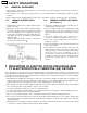
2 PREVENTION OF ELECTRO STATIC DISCHARGE (ESD) TO
ELECTROSTATICALLY SENSITIVE (ES) DEVICES
4
3 PRECAUTION OF LASER DIODE
5
4 HANDLING PRECAUTIONS FOR TRAVERSE DECK
5
4.1. Handling of optical pickup
5
4.2. Grounding for electrostatic breakdown prevention
5
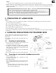
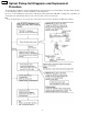
5 Optical Pickup Self-Diagnosis and Replacement Procedure
6
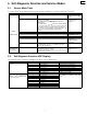
6 Self-Diagnosis Function and Service Modes
7
6.1. Service Mode Table
7
6.2. Self-Diagnosis Function (UHF Display)
7
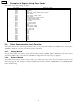
6.3. Examples of Repairs Using Error Codes
8
6.4. Sales Demonstration Lock Function
8
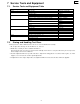
7 Service Tools and Equipment
9
7.1. Service Tools and Equipment Table
9
7.2. Storing and Handling Test Discs
9
8 General Description
10
8.1. Operating Instructions
10
9 Assembling and Disassembling the Casing and Checking
P.C.B.s
11
9.1. Disassembly Procedure
11
9.2. Casing Parts and P.C.B. Positions
12
9.3. Service Positions
12
9.4. Disassembling the Top Cover
13
9.5. Disassembling the Tray
13
9.6. Disassembling the Front Panel
13
9.7. Disassembling the Loading Base Unit
14
9.8. Checking the Module P.C.B.
14
9.9. Disassembling the Rear Panel
14
9.10. Checking the Power Supply P.C.B.
15
9.11. Checking the Mother P.C.B.
15
9.12. Checking the Front Switch P.C.B.
16
9.13. Checking the Power Switch P.C.B.
16
10 Service Precautions
17
10.1. Initializing the DVD Player
17
10.2. Handling After Completing Repairs
17
11 Assembling and Disassembling the Optical Pickup
(Mechanical Parts)
18
11.1. Handling the Optical Pickup
18
11.2. Disassembly Procedure
18
11.3. Disassembling the Clamp Base Unit
19
11.4. Disassembling the Clamper Weight, Clamper Yoke,
Magnet and Clamper
19
11.5. Disassembling the Traverse Unit
19
11.6. Disassembling the Stepping Motor Unit
20
11.7. Disassembling the Optical Pickup Unit
20
11.8. Disassembling the Nut Unit
21
11.9. Disassembling the Sub-Shaft Preload Spring
21
11.10. Assembling the Optical Pickup
21
11.11. Disassembling the Spindle Motor Unit
22
11.12. Optical Pickup Tilt Adjustment
23
11.13. Disassembling the Intermediate Chassis
25
11.14. Disassembling the Vertical cam and Drive gear
25
11.15. Disassembling the Pulley Gear and Deceleration Gear
25
11.16. Disassembling the Mechanism Loading P.C.B.
25
12 Electrical Adjustment
26
12.1. Video Output (Luminance Signal) Adjustment
26
12.2. Video Output (Chrominance Signal) Adjustment
26
12.3. Video Component Signal (CB) Output Adjustment
27
13 Abbreviations
28
14 VOLTAGE CHART
30
14.1. POWER SUPPLY P.C.B.
30
14.2. MODULE P.C.B.
30
14.3. MOTHER P.C.B.
33
15 BLOCK DIAGRAM
35
15.1. OVERALL BLOCK DIAGRAM
35
15.2. SERVO BLOCK DIAGRAM
36
15.3. VIDEO BLOCK DIAGRAM
37
15.4. AUDIO BLOCK DIAGRAM
38
16 SCHEMATIC DIAGRAM
39
16.1. INTERCONNECTION SCHEMATIC DIAGRAM
39
16.2. POWER SUPPLY SCHEMATIC DIAGRAM
40
16.3. ADSC SECTION (MODULE P.C.B. (1/7)) SCHEMATIC
DIAGRAM
41
16.4. AV DECORDER SECTION (MODULE P.C.B. (2/7))
SCHEMATIC DIAGRAM
42
16.5. VIDEO D/A CONVERTER SECTION (MODULE P.C.B.
(3/7)) SCHEMATIC DIAGRAM
43
16.6. AUDIO SECTION (MODULE P.C.B. (4/7)) SCHEMATIC
DIAGRAM
44
16.7. FEP SECTION (MODULE P.C.B. (5/7)) SCHEMATIC
DIAGRAM
45
16.8. CPU SECTION (MODULE P.C.B. (6/7)) SCHEMATIC
DIAGRAM
46
16.9. ODC SECTION (MODULE P.C.B. (7/7)) SCHEMATIC
DIAGRAM
47
16.10. VIDEO OUT SECTION (MOTHER P.C.B. (1/3))
SCHEMATIC DIAGRAM
48
CONTENTS
Page Page
2
DVD-RV60