
Datasheet

Design and specifications are each subject to change without notice. Ask factory for the current technical specifications before purchase and/or use.
Should a safety concern arise regarding this product, please be sure to contact us immediately.
Plastic Film Capacitors
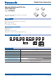
1 2 3 4 5 6 7 8 9 10 11
E C H U 1 C
Product code Dielectric &
construction
Rated voltage Cap. Tol. SuffixSuffixCapacitance
Code
9
V
Tape width
12 mm
16 mm
G
J
±2 %
±5 %
1 100 V.DC
Features
●
Small in size
●
Low loss and excellent frequency characteristics
●
For refl ow soldering
●
RoHS directive compliant
●
Time-constant
●
Filtering
●
Oscillation and resonance
●
Resonance circuit for LCD backlight inverter unit
Stacked metallized PPS fi lm as dielectric with simple
mold-less construction
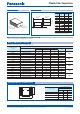
Stacked Metallized PPS Film
Chip Capacitor
Type : ECHU(C)
Category temp. range
(Including temperature-rise on unit surface)
– 55 °C to +105 °C
Rated voltage 100 V.DC
Capacitance range 0.010 µF to 0.22 µF (E12)
Capacitance tolerance ±2 %(G), ±5 %(J)
Dissipation factor (tan
d
) tan d < 0.6 % (20 °C, 1 kHz)
Withstand voltage Between terminals : Rated volt. (V.DC)×150 %, 60 s
Insulation resistance (IR) IR > 3000 MΩ (20 °C, 100 V.DC, 60 s)
Soldering conditions
Refl ow soldering : 260 °C max. and 95 sec max. at more than 220 °C
(Temp. at capacitor surface)
✽
In case of applying voltage in alternating current (50 Hz or 60 Hz sine wave) to a capacitor with DC rated voltage,
please refer to the page of “Permissible voltage (R.M.S) in alternating current corresponding to DC rated voltage”.
Explanation of part number
Speci cations
Recommended applications
Feb. 201601