
Datasheet

Design and specifications are each subject to change without notice. Ask factory for the current technical specifications before purchase and/or use.
Should a safety concern arise regarding this product, please be sure to contact us immediately.
Plastic Film Capacitors
1 2 3 4 5 6 7 8 9 10 11 12
E C H U X
Product code Dielectric &
construction
Rated voltage Cap. Tol. SuffixSuffixCapacitance
Code
5
9
Tape width
8 mm
✽ Tape width 8 mm
and diameter
f330 mm reel is
prepared
12 mm
Reel diameter
f180 mm
f330 mm
G
J
±2 %
±5 %
1C
1H
16 V.DC
50 V.DC
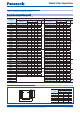
Element
(Stacked)
Outer electrode
L±0.2
(±0.3)
(±0.15)
W±0.2
H±0.2
(±0.15)
e±0.30
(±0.25)
(±0.20)
g
✽ ✽
✽ ✽ ✽
✽ ✽
e±0.30
(±0.25)
(±0.20)
✽
✽ ✽
✽
✽ ✽ ✽
✽
To be applied only for size code J1, J2
✽✽
To be applied only for size code K1
✽✽✽
To be applied only for size code E1, E2, D1, D3, D4
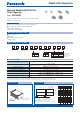
Features
●
Small in size (Minimum size 1.6 mm × 0.8 mm)
●
85 °C, 85 %RH, W.V. × 1.0 for 500 hours
●
For refl ow soldering
●
RoHS directive compliant
●
Time-constant
●
Filtering
●
Oscillation and resonance
●
Audio circuit
Stacked metallized PPS fi lm as dielectric with simple
mold-less construction
Explanation of part number
Speci cations
Construction Dimensions
Stacked Metallized PPS Film
Chip Capacitor
Type : ECHU(X)
Category temp. range
(Including temperature-rise on unit surface)
– 55 °C to +125 °C
Rated voltage
16 V.DC, 50 V.DC
(50 V.DC : 0.12 F or more : Derating or rated voltage by 1.25 % / °C at more than 105 °C)
Capacitance range 0.00010 µF to 0.22 µF (E12)
Capacitance tolerance ±2 %(G), ±5 %(J)
Dissipation factor (tan
d
) tan d < 0.6 % (20 °C, 1 kHz)
Withstand voltage Between terminals : Rated volt. (V.DC)×150 %, 60 s
Insulation resistance (IR)
16 V.DC : IR > 3000 MΩ (20 °C, 10 V.DC, 60 s)
50 V.DC : IR > 3000 MΩ (20 °C, 50 V.DC, 60 s)
Soldering conditions
Refl ow soldering : 260 °C max. and 95 sec max. at more than 220 °C (Temp. at capacitor surface)
✽
Please consult us for fl ow soldering
✽
In case of applying voltage in alternating current (50 Hz or 60 Hz sine wave) to a capacitor with DC rated voltage,
please refer to the page of “Permissible voltage (R.M.S) in alternating current corresponding to DC rated voltage”.
Size code
LWHe g
K1 1.6 0.8 0.7 0.35
> 0.4
J1 2.0 1.25 0.9 0.45
> 0.6
J2 2.0 1.25 1.1 0.45
> 0.6
H1 3.2 1.6 0.9 0.65
> 1.0
H2 3.2 1.6 1.1 0.65
> 1.0
H3 3.2 1.6 1.5 0.65
> 1.0
G1 3.2 2.5 1.1 0.65
> 1.0
G2 3.2 2.5 1.5 0.65
> 1.0
G3 3.2 2.5 2.1 0.65
> 1.0
E1 4.8 3.3 1.5 0.80
> 2.0
E2 4.8 3.3 2.1 0.80
> 2.0
D1 6.0 4.1 1.9 0.80
> 2.0
D3 6.0 4.1 2.5 0.80
> 2.0
D4 6.0 4.1 2.8 0.80
> 2.0
Unit : mm
Recommended applications
Feb. 201601