
Datasheet

– EC9 –
Design and specifi cations are each subject to change without notice. Ask factory for the current technical specifi cations before purchase and/or use.
Should a safety concern arise regarding this product, please be sure to contact us immediately.
Multilayer Ceramic Capacitors(For General Usage)
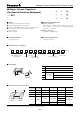
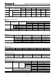
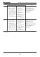
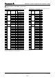
■ Packaging Styles and Standard Packaging Quantities
Quantity (Taping: pcs./reel)
Packaging
Style
Code
Size
Thickness (mm)
Packaging Styles
0201 0402 0603 0805
T=0.3 T=0.5 T=0.8 T=0.6 T=0.85 T=1.25
E
φ
180
reel
Paper taping
(Pitch: 2 mm)
15,000 10,000 — — — —
V
Paper taping
(Pitch: 4 mm)
——4,000 5,000 4,000 —
F
Embossed taping
(Pitch: 4 mm)
—————3,000
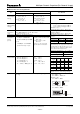
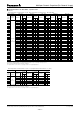
■ Temperature Characteristics
● Class 1
Temperature
Characteristic
Code
Temperature
Characteristics
Temp. Coeff.
(ppm/°C)
Rate of Capacitance change at each Temperature (%)
–25 °C 85 °C
max. min. max. min.
CC
∆
>
10 pF CG 0± 30 0.33 –0.14 0.20 –0.20
>
4 pF CH 0± 60 0.49 –0.27 0.39 –0.39
3 pF CJ 0±120 0.82 –0.54 0.78 –0.78
<
2 pF CK 0±250 1.54 –1.13 1.63 –1.63
GSL+350 to –1000 — — 2.28 –6.50
Temperature coef fi cient: calculated between 20 °C to 85 °C
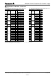
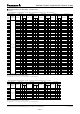
For applicable “temperature characteristics”, see the lists of standard products on page 13 to 19.
● Class 2
Temperature
Characteristic Code
Temperature
Characteristics
Capacitance Change
Measurement
Temperature Range
Reference
Temperature
B
B±10 %–25 to 85 °C 20 °C
X7R ±15 % –55 to 125 °C 25 °C
X5R ±15 % –55 to 85 °C 25 °C
F
F+30, –80 % –25 to 85 °C 20 °C
Y5V +22, –82 % –30 to 85 °C 25 °C
For applicable “temperature characteristics”, see the lists of standard products on page 13 to 19.
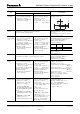
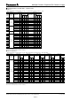
■ Rated Voltage
Code 1H 1E 1C 1A 0J
Rated Voltage DC 50 V DC 25 V DC 16 V DC 10 V DC 6.3 V
■ Nominal Capacitance
Ex 0R5 010 100 104
Nominal
Capacitance
0.5 pF 1 pF 10 pF
100,000 pF
(0.1 µF)
■ Capacitance Tolerance
Class Temperature Characteristics Tol. Code Capacitance Tolerance
1C
∆
, SL
Capacitance
range
C
<
5 pF C ±0.25 pF
C
<
10 pF D ±0.5 pF
C =10 pF F ±1 pF
C
>
10 pF
J±5 %
K±10 %
2
B, X7R, X5R
K±10 %
M±20 %
F, Y5V
Z
+80, –20 %
φ
330 reel and bulk case type : Please contact us
Sep. 200800