
Datasheet


– EC11 –
Design and specifi cations are each subject to change without notice. Ask factory for the current technical specifi cations before purchase and/or use.
Should a safety concern arise regarding this product, please be sure to contact us immediately.
Multilayer Ceramic Capacitors(For General Usage)
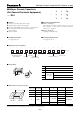
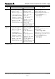
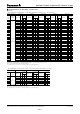
20
45±245±2
Bending Value
Unit : mm
R340
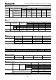
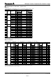
Item
Specifi cation
Test Method
Class 1 Class 2
Bending
Strength
Appearance:
No mechanical damage
Capacitance change:
Within ±5 % or ±0.5 pF
whichever is larger.
Appearance:
No mechanical damage
Capacitance change:
Temp. Char.
B, X7R, X5R : within ±12.5 %
F ,Y5V : within ±30 %
Bending value:1 mm
Bending speed:1 mm/
Vibration
Proof
Appearance: No mechanical damage.
Capacitance: within the specifi ed tolerance
Q, tan
δ
: Initial standard value
Total amplitude : 1.5 mm
Vibration frequency : 10 to 55 to 10 Hz
for 1 min.
3 perpendicular directions for 2 hours
each, a total of 6 hours
Resistance
to Soldering
Heat
Appearance:
No mechanical damage
Capacitance change:
Within ±2.5 % or ±0.25 pF
whichever is larger.
Q.tan
δ
:Initial standard value
IR:Initial standard value
Withstand voltage:
No dielectric breakdown
and/or damage
Appearance:
No mechanical damage
Capacitance change:
Temp. Char.
B, X7R, X5R : within ±7.5 %
F, Y5V : within ±20 %
tan
δ
:Initial standard value
IR:Initial standard value
Withstand voltage:
No dielectric breakdown
and/or damage
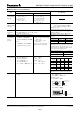
Soldering bath method
Preconditioning:Heat treatment/Class 2
(
✽
1)
Solder temperature:270±5 °C
Dipping period:3.0±0.5 s
Preheat condition:
Order Temp. (°C) Size 0805 max.
180 to 100120 to 180 s
2150 to 200120 to 180 s
Recovery (Standard condition):
Class 1:24±2 h
Class 2:48±4 h
Solderability More than 95 % of the soldered area of both terminal
electrodes should be covered with fresh solder.
Soldering bath method
Solder temperature:230±5 °C
Dipping period:4±1 s
Solder:H63A (JIS Z 3282)
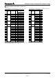
Temperature
Cycle
Appearance:
No mechanical damage
Capacitance change:
Within ±2.5 % or ±0.25 pF
whichever is larger.
Q.tan
δ
:Initial standard value
IR:Initial standard value
Withstand voltage:
No dielectric breakdown
and/or damage
Appearance:
No mechanical damage
Capacitance change:
Temp. Char.
B, X7R, X5R : within ±7.5 %
F, Y5V : within ±20 %
tan
δ
:Initial standard value
IR:Initial standard value
Withstand voltage:
No dielectric breakdown
and/or damage
Preconditioning:Heat treatment
(150 °C, 1h) /Class 2
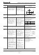
Condition of one cycle
Step 1:Minimum operationing temp.
30±3 min
Step 2:Room temp. 3 min max.
Step 3:Maximum operationing temp.
30±3 min
Step 4:Room temp. 3 min max.
Number of cycles:5 cycles
Recovery (Standard condition)
Class 1:24±2 h
Class 2:48±4 h
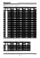
Damp Heat
(Steady state)
Appearance:
No mechanical damage
Capacitance change:
Within ±5 % or ±0.5 pF
whichever is larger.
Q:
C
<
10 pF:Q
>
200+10C
10 pF
<
C<30 pF:Q
>
275
+
5C/2
30 pF
<
C
<
1000 pF:Q
>
350
tan
δ
:
C>1000 pF:tan
δ
<
0.004
C:Nominal capacitance in pF
IR:
1000 M
액
or 50/C (M
액
)
Whichever is less.
C:Nominal capacitance in µF
Appearance:
No mechanical damage
Capacitance change:
Temp. Char.
B, X7R, X5R: Within ±20 %
F, Y5V: Within ±30 %
tan
δ
:
Temp. Char.
B, X7R, X5R: 0.25 max.
F, Y5V: 0.3 max.
IR:
1000 M
액
or 50/C (M
액
)
Whichever is less.
Note:10/C (M
액
) min. for DC 10 V max.
C:Nominal capacitance in µF
Please see the technical
specifi cations for details.
Preconditioning:Heat treatment/Class 2
(
✽
1)
Temperature:40±2 °C
Relative humidity:90 to 95 %
Test period:500+24/0 h
Recovery (Standard condition)
Class 1:24±2 h
Class 2:48±4 h
(
✽
1) Heat treatment: 1 h of heat treatment at 150 +0/-10 °C followed by 48±4 h recovery under standard conditions.
Sep. 200800