
Datasheet


Design and specifi cations are each subject to change without notice. Ask factory for the current technical specifi cations before purchase and/or use.
Should a safety concern arise regarding this product, please be sure to contact us immediately.
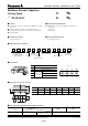
Multilayer Ceramic Capacitors(4 Array Type)
– EC29 –
Temperature
Characteristic Code
Temperature
Characteristics
Temp. Coeff.
(ppm/°C)
Rate of Capacitance change at each Temp. (%)
–25 °C 85 °C
max. min. max. min.
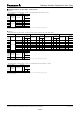
CCH0 ± 60 0.49 –0.27 0.39 –0.39
■ Temperature Characteristics
● Class 1
● Class 2
Temperature
Characteristic Code
Temperature
Characteristics
Capacitance Change
Measurement
Temperature Range
Reference Temperature
B
B±10 %–25 to 85 °C 20 °C
X7R ±15 % –55 to 125 °C 25 °C
X5R ±15 % –55 to 85 °C 25 °C
F
F+30, –80 % –25 to 85 °C 20 °C
Y5V +22, –82 % –30 to 85 °C 25 °C
■ Rated Voltage
Code 1H 1E 1C 1A 0J
Rated Voltage DC 50 V DC 25 V DC 16 V DC 10 V DC 6.3 V
■ Nominal Capacitance
Ex. 100 101104105
Nominal
Capacitance
10 pF 100 pF
100,000 pF
(0.1 µF)
1,000,000 pF
(1.0 µF)
Class Temperature Characteristics Tolerance Code Capacitance Tolerance
1CHCapacitance range
C=10 pF F±1 pF
C>10 pF K ±10 %
2
B, X7R, X5R M ±20 %
F, Y5V Z +80, –20 %
■ Capacitance tolerance
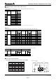
■ Specifi cations and Testing Methods
Item
Specifi cations
Test Method
Class 1 Class 2
Operating
Temperature
Range
Temp. Char.
CH: –55 to 125 °C
Temp. Char.
B, X7R: –55 to 125 °C
X5R: –55 to 85 °C
F, Y5V: – 3 0 to 85 °C
———
Dielectric
Withstanding
Voltage
No dielectric breakdown and/or damage Test voltage:
Class 1: Rated voltage
҂
300 %
Class 2: Rated voltage
҂
250 %
Duration: 1 to 5 s
Charge/discharge current: 50 mA max.
Insulation
Resistance (IR)
10000 M
액
or 500/C (M
액
) Whichever is less
Note: 100/C (M
액
) min. for DC 10 V max.
C: Nominal Cap. in µF
Measuring voltage: Rated voltage
Duration: 60±5 s
Charge/discharge current: 50 mA max.
Capacitance Within the specifi ed tolerance Measuring temperature: 20±2 °C
Class 1
Measuring frequency1 MHz ± 10 %
Measuring voltage0.5 to 5 Vrms
Class 2
Preconditioning: The capacitors shall be
kept in temperature of 150 +0/–10 ± for 1
hour and subject to standard conditions
✽
for 48±4 hours before initial measurement.
Measuring frequency1 kHz ± 10 %
Measuring voltage1.0±0.2 Vrms
Q Factor or
Dissipation Factor
(tan
δ
)
Q:
C < 30 pF: Q
>
400+20 C
30 pF
<
C
<
1000 pF:
Q
>
1000
C: Nominal Cap. in pF
tan
δ
:
Temp. Char.
B, X7R: 0.025 max.
X5R: 0.075 max.
F, Y5V: 0.125 max.
Please see the technical
specifi cations for details.
✽
Standard condition: Temperature 15 to 35 °C, Relative humidity 45 to 75 %.
For further information, see the technical specifi cations.
Temperature coeffi cient: calculated between 20 °C to 85 °C
For applicable “temperature characteristics”, see the lists of standard products on page 31 to 32.
00 Sep. 2008