
Datasheet

Design and specifications are each subject to change without notice. Ask factory for the current technical specifications before purchase and/or use.
Should a safety concern arise regarding this product, please be sure to contact us immediately.
Plastic Film Capacitors
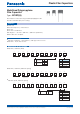
T max.
0d±0.05
Copper-wire or
Copper-clad
steel-wire
L max.
Marking
G max.
H max.25 min.
F±1.0
Straight
Crimped lead
(Suffix B)
L max.
H max.
S±0.8
4.5±0.5
Marking
Crimped lead
(Suffix Q)
Cut lead
(Suffix C)
L max.
S±0.8
Marking
H max.
4.5±0.5
4.5±0.5
Marking
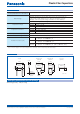
Style B Style D
●
Packing quantity : 100 pcs./bag
Packaging speci cations for bulk package
Category temp. range
(Including temperature-rise on unit surface)
– 40 °C to +105 °C
Rated voltage
250 V.DC
450 V.DC (Derating of rated voltage by 1.25%/°C at more than 85 °C)
Peak to peak voltage applied on the capacitor should be less than
240 Vp-p, and zero to peak voltage should be less than 450 Vo-p.
630 V.DC (Derating of rated voltage by 1.0%/°C at more than 85 °C)
Capacitance range
250 V.DC 0.1 F to 6.8 F
450 V.DC 0.1 F to 4.7 F
630 V.DC 0.1 F to 2.2 F
Capacitance tolerance
250 V.DC ±3 %(H), ±5 %(J)
450 V.DC ±5 %(J), ±10 %(K)
630 V.DC ±5 %(J)
Dissipation factor (tan d) tan d < 0.1 % (20 °C, 1 kHz)
Withstand voltage Between terminals : Rated volt. (V.DC)×150 %, 60 s
Insulation resistance (IR)
250 V.DC
C < 0.33 F : IR > 9000 MΩ
(20 °C, 100 V.DC, 60 s)
C > 0.33 F : IR > 3000 MΩ µF
450 V.DC
C < 0.33 F : IR > 30000 MΩ
(20 °C, 100 V.DC, 60 s)
C > 0.33 F : IR > 10000 MΩ µF
630 V.DC
C < 0.33 F : IR > 9000 MΩ
(20 °C, 500 V.DC, 60 s)
C > 0.33 F : IR > 3000 MΩ µF
✽
In case of applying voltage in alternating current (50 Hz or 60 Hz sine wave) to a capacitor with DC rated voltage,
please refer to the page of “Permissible voltage (R.M.S) in alternating current corresponding to DC rated voltage”.
Unit : mm
Speci cations
Dimensions
Feb. 201601