
Datasheet

Design and specifications are each subject to change without notice. Ask factory for the current technical specifications before purchase and/or use.
Should a safety concern arise regarding this product, please be sure to contact us immediately.
Plastic Film Capacitors
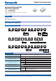
1 2 3 4 5 6 7 8 9 10 11
E C W U
12
C
Product code Dielectric &
construction
Rated voltage Cap. Tol. SuffixSuffixCapacitance
Code
9
V
Tape width
12 mm
16 mm
J
K
±5 %
±10 %
2 250 V.DC
1 100 V.DC
1 2 3 4 5 6 7 8 9 10 11
E C W U 1104V33
Product code Dielectric &
construction
Rated voltage Capacitance Suffix
1 100 V.DC Small in size, Cap. Tol. : ±5 %, Tape width : 12 mm
1 2 3 4 5 6 7 8 9 10 11
E C W U C 2J
12
JV
Product code Dielectric &
construction
Rated voltage Cap. Tol. SuffixSuffix Capacitance
Code
V
Tape width
16 mm
J ±5 %
2J 630 V.DC
Stacked metallized PEN fi lm as dielectric with simple
mold-less construction
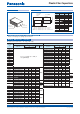
Stacked Metallized PEN
Film Chip Capacitor
Type : ECWU(C)
Category temp. range
(Including temperature-rise on unit surface)
– 55 °C to +125 °C
Rated voltage
100 V.DC, 250 V.DC, 630 V.DC (Derating of rated voltage by 1.25 %/°C more than 85 °C)
Capacitance range
100 V.DC 0.012 F to 1.0 F (E12)
250 V.DC 0.0010 F to 0.12 F (E12)
630 V.DC 0.022 F, 0.027 F, 0.033 F
Capacitance tolerance
100 V.DC ±5 %(J), ±10 %(K) (C > 0.18 F : ±10 %(K) Only)
250 V.DC ±5 %(J), ±10 %(K)
630 V.DC ±5 %(J)
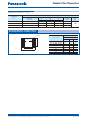
Dissipation factor (tan d) tan d < 1.0 % (20 °C, 1 kHz)
Withstand voltage Between terminals : Rated volt. (V.DC)×150 %, 60 s
Insulation resistance (IR)
C < 0.33 F
100 V.DC, 250 V.DC, 630 V.DC : IR > 3000 MΩ (20 °C, 100 V.DC, 60 s)
C > 0.33 F 100 V.DC : IR > 1000 MΩF (20 °C, 100 V.DC, 60 s)
Soldering conditions
100 V.DC
250 V.DC
Refl ow soldering : 250 °C max. and 60 s max. at more than 220 °C
(Temp. at capacitor surface)
630 V.DC
Refl ow soldering : 250 °C max. and 60 s to 150 s. at more than 217 °C (Temp. at cap. surface)
✽
In case of applying voltage in alternating current (50 Hz or 60 Hz sine wave) to a capacitor with DC rated voltage,
please refer to the page of “Permissible voltage (R.M.S) in alternating current corresponding to DC rated voltage”.
✽
Please consult us for capacitance range between 0.15 F and 1.0 F. (250 V.DC)
●
Small in size
●
For refl ow soldering
●
RoHS directive compliant
●
General purpose (Coupling, By-pass)
Features
Recommended applications
Explanation of part number
Speci cations
Feb. 201601