
Datasheet

Design and specifications are each subject to change without notice. Ask factory for the current technical specifications before purchase and/or use.
Should a safety concern arise regarding this product, please be sure to contact us immediately.
Electric Double Layer Capacitors (Gold Capacitor)
P
0
fD
0
P
1
F
P
2
P
5.4±0.8
fd
H
1
13.4 max.
H
0
W
W
1
W
2
W
0
△h
–
+
–
+
△h
1
10.5 max.
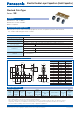
Stacked Coin Type
Series : SE
Dimensions in mm(not to scale)
Characteristics list
(Unit : mm)
●
Endurance : +70 °C 1000 h
●
Automatic insertion available
●
RoHS compliant
●
Memory back-up for video and audio equipment,cameras, telephones, printers, data terminals,
rice cookers and intelligent remote controls.
+0.8
–0.2
Dimensions Nominal Tolerance
0
d 0.55 ±0.05
P
0
12.7 ±0.2
F 5.0
W 18.0 ±0.5
W
0
5.5
<
–
W
1
9.0 ±0.5
W
2
0 to 3.0 –
H
0
16.4 ±0.5
0
D
0
4.0 ±0.2
P 12.7 ±1.0
P
1
3.85 ±0.50
P
2
6.35 ±1.00
△h, △h
1
0 ±1.0
H
1
30.3
>
–
Features
Recommended applications
Speci cations
Category temp. range –25 °C to +70 °C
Maximum operating voltage 5.5 V.DC
Nominal cap.range 0.22 F
Characteristics at
low temperature
Capacitance change ±30 % of initial measured value at +20 °C (at –25 °C)
Internal resistance
<
5 times of initial measured value at +20 °C (at –25 °C)
Endurance
After 1000 hours application of 5.5 V.DC at +70 °C, the capacitor shall meet the following limits.
Capacitance change ±30 % of initial measured value
Internal resistance
<
4 times of initial specifi ed value
Shelf life
After 1000 hours storage at +70 °C without load, the capacitor shall meet the specifi ed
limits for Endurance.
✽
1 The recommended discharge current is a reference value. Please design your equipment (circuit) in consideration of IR drop.
∙ When ordering please observe the minimum packaging quantity.
∙ When the surface mount component goes through UV or a heat oven to affi x the adhesive glue, the capacitor’s surface
temperature should not exceed 100 °C for more than 60 seconds (maximum tem per a ture should not exceed 105 °C)
∙ Do not use refl ow soldering. Please refer to the page of “Application guidelines”.
Category
temp.
range
(°C)
Maximum
operating
voltage
(V.DC)
Capacitance
(F)
Capacitance
tolerance
(F)
Internal
resistance
(Initial specifi ed value)
(Ω) at 1 kHz
Recommended
✽1
discharge current
(μA)
Parts number
Mass
(Reference value)
(g)
Min.
packaging
q'ty
(pcs)
–25 to +70
5.5
0.22 0.176 to 0.396
<
75
300 or less EECSE0H224 1.0 1000
Aug. 201606