
Datasheet

Design and specifications are each subject to change without notice. Ask factory for the current technical specifications before purchase and/or use.
Should a safety concern arise regarding this product, please be sure to contact us immediately.
Aluminum Electrolytic Capacitors (SMD Type)
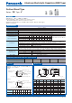
A±0.2
W
( ) Reference size
L
0D±0.5
H
B±0.2
(I)
K
(P)
(I)
+
–
0.3 max.
Pressure Relief (010 and larger)
22
FKj
Capacitance (µF)
Rated Voltage code
Series identification
Mark for Lead-Free
products
(Black dot)
Lot number
Negative polarity
marking (–)
3300
FKj
Capacitance (µF)
Rated Voltage code
Series identification
Lot number
Negative polarity
marking (–)
Frequency correction factor for ripple current
●
Endurance : 105 °C 2000 h to 5000 h
●
Low impedance (40 % to 60 % less than FC series)
Miniaturized (30 % to 50 % less than FC series)
●
Vibration-proof product is available upon request. (08 mm and larger)
●
RoHS compliant
Features
Speci cations
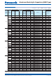
(Unit : mm)
Surface Mount Type
Series : FK Type : V
Category temperature range
–55 °C to +105 °C
Rated voltage range 6.3 V.DC to 100 V.DC
Capacitance range 3.3 µF to 6800 µF
Capacitance tolerance ±20 % (120 Hz/+20 °C)
Leakage cur rent I < 0.01 CV or 3 (µA) After 2 minutes (Whichever is greater)
Dissipation factor (tan d)
Please see the attached characteristics list
Characteristics
at low temperature
V.DC 6.3 10 16 25 35 50 63 80 100
(Impedance ratio at 120 Hz)
Z(–25 °C)/Z(+20 °C)
222222222
Z(–40 °C)/Z(+20 °C)
333333333
Z(–55 °C)/Z(+20 °C)
444333333
Endurance
After applying rated working voltage for 2000 hours at +105 °C±2 °C and then being stabilized at +20 °C,
Capacitors shall meet the following limits. ( > 012.5 and suffi x “G” in 08×10.2, 010×10.2 are 5000 hours)
Capacitance change Within ±30 % of the initial value (Suffi x “G” is 35 %)
tan d
< 200 % of the initial limit (Suffi x “G” is 300 %)
DC leakage current Within the initial limit
Shelf life
After storage for 1000 hours at +105 °C±2 °C with no voltage applied and then being stabilized
at +20 °C, capacitors shall meet the limits specifi ed in Endurance (With voltage treatment)
Resistance to
soldering heat
After refl ow soldering and then being stabilized at +20 °C, capacitors shall meet the following limits.
Capacitance change Within ±10 % of the initial value
tan d Within the initial limit
DC leakage current Within the initial limit
AEC-Q200 AEC-Q200 compliant
Example : 6.3 V.DC 22 µF, 6.3 V.DC 3300 µF
Marking color : BLACK
< 010
> 012.5
Size
code
0D
LA,BH I W P K
B 4.0 5.8±0.3 4.3 5.5 max. 1.8 0.65±0.1 1.0 0.35
- 0.2
C 5.0 5.8±0.3 5.3 6.5 max. 2.2 0.65±0.1 1.5 0.35
- 0.2
D 6.3 5.8±0.3 6.6 7.8 max. 2.6 0.65±0.1 1.8 0.35
- 0.2
D8 6.3 7.7±0.3 6.6 7.8 max. 2.6 0.65±0.1 1.8 0.35
- 0.2
E 8.0 6.2±0.3 8.3 9.5 max. 3.4 0.65±0.1 2.2 0.35
- 0.2
F 8.0 10.2±0.3 8.3 10.0 max. 3.4 0.90±0.2 3.1 0.70±0.2
G 10.0 10.2±0.3 10.3 12.0 max. 3.5 0.90±0.2 4.6 0.70±0.2
H13 12.5 13.5±0.5 13.5 15.0 max. 4.7 0.90±0.3 4.4 0.70±0.3
J16 16.0 16.5±0.5 17.0 19.0 max. 5.5 1.20±0.3 6.7 0.70±0.3
K16 18.0 16.5±0.5 19.0 21.0 max. 6.7 1.20±0.3 6.7 0.70±0.3
+1. 5
+1. 5
+1. 5
+1. 5
+1. 5
Frequency (Hz) 50, 60 120 1 k 10 k 100 k to
Correction factor 0.70 0.75 0.90 0.95 1.00
DimensionsMarking
R. Voltage
(V.DC)
6.3 10 16 25 35 50 63 80
100
Code j ACEVHJK2A
Mar. 201602