
Datasheet

Design and specifi cations are each subject to change without notice. Ask factory for the current technical specifi cations before purchase and/or use.
Should a safety concern arise regarding this product, please be sure to contact us immediately.
Conductive Polymer Hybrid Aluminum Electrolytic Capacitors/ZA
– EEE-2 –
33
ZAE
Capacitance (μF)
Rated Voltage Mark
Series identification
Lot number
Negative polarity marking (–)
A±0.2
W
( ) Reference size
L
0D±0.5
H
B±0.2
(I)
K
(P)
(I)
+
–
0.3 max.
Pressure Relief (010 and larger)
■ Features
●
Endurance: 10000 h at 105 °C
●
Low ESR and High ripple current
(70 % over, Lower ESR than Current V-FP)
●
High voltage (to 80 V)
●
Equivalent to conductive polymer type Aluminum Electrolytic Capacitor
(There are little characteristics change by temperature and frequency)
●
Vibration-proof product is available upon request. (
0
8 mm and larger)
● AEC-Q200 qualifi ed
✽
●
RoHS directive compliant
Surface Mount Type
Series:
ZA
Type:
V
High temperature Lead-Free re ow
■ Speci cations
Category Temp. Range –55 °C to +105 °C
Rated W.V.Range 25 V.DC to 80 V.DC
Nominal Cap.Range 10 μF to 330 μF
Capacitance Tolerance ±20 % (120 Hz/+20 °C)
DC Leakage Cur rent I
<
0.01 CV or 3 (μA) After 2 minutes (whichever is greater)
tan
d
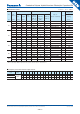
Please see the attached Standard Products list
Endurance
The capacitor shall be subjected to application of the D.C. voltage with full rated ripple current at +105 °C for 10000
hours. After stabilizing at room temperature(+15 to 35 °C), the capacitor shall not exceed the specifi ed limits.
(The sum of DC voltage and ripple peak voltage shall not exceed the rated voltage.)
Capacitance change ±30 % of initial measured value
tan
d
<
200 % of initial specifi ed value
E. S. R.
<
200 % of initial specifi ed value
DC leakage current
<
initial specifi ed value
ESR after Endurance
(Ω/100 kHz) (–40 °C)
Size Code
CDD8FG
2.0 1.4 0.8 0.4 0.3
Shelf Life
After storage for 1000 hours at +105 °C±2 °C with no voltage applied and then being stabilized at +20 °C,
capacitors shall meet the limits specifi ed in Endurance. (With voltage treatment)
Damp Heat (Load)
After applying rated working voltage for 2000 hours at +85 °C±2 °C / 85% to 90%RH and then being stabilized
at +20 °C, Capacitors shall meet the following limits.
Capacitance change ±30 % of initial measured value
tan
d
<
200 % of initial specifi ed value
E. S. R.
<
200 % of initial specifi ed value
DC leakage current
<
initial specifi ed value
Resistance to
Soldering Heat
After refl ow soldering and then being stabilized at +20 °C, capacitors shall meet the following limits.
Capacitance change ±10 % of initial measured value
tan
d
<
initial specifi ed value
DC leakage current
<
initial specifi ed value
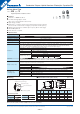
■ Di men sions in mm (not to scale)■ Marking
Example:25 V 33 μF Marking color : BLACK
Rated Voltage Mark
Size
code
D L A, B H I W P K
C 5.0 5.8±0.3 5.3 6.5 max. 2.2 0.65±0.1 1.5 0.35
- 0.20
D 6.3 5.8±0.3 6.6 7.8 max. 2.6 0.65±0.1 1.8 0.35
- 0.20
D8 6.3 7.7±0.3 6.6 7.8 max. 2.6 0.65±0.1 1.8 0.35
- 0.20
F 8.0 10.2±0.3 8.3 10.0 max. 3.4 0.90±0.2 3.1 0.70±0.2
G 10.0 10.2±0.3 10.3 12.0 max. 3.5 0.90±0.2 4.6 0.70±0.2
+ 0.15
+ 0.15
+ 0.15
E 25 V
V 35 V
H 50 V
J 63 V
K 80 V
(Unit : mm)
✽
This product qualify for AEC-Q200, but it has some deviations.
03 Dec. 2014