
Datasheet

-55 to +105°C
6.3 to 100V .DC
3.3 to 6800 µ F
±20 % (120Hz/+20°C)
I 0.01 CV or 3(µA)
After 2 minutes application of rated working voltage at +20°C.
( Whichever is greater )
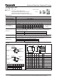
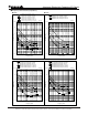
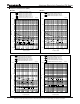
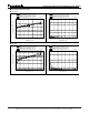
n Dimensions in mm (not to scale)
n Marking
( ) reference size
Surface Mount Type
n Features
Endurance: 2000 to 5000h at105°C
Low impedance (40 to 60% less than FCseries)
Miniaturization(30 to 50% less than FC series)
Vibration-proof product is available upon request.(f8
<
)
n Specifications
Category temp. range
Rated W.V. Range
Nominal Cap. Range
Capacitance Tolerance
DC Leakage Current
tan d
Marking color : BLACK
Example.16V10µF
W.V. (V) 6.3 10 16 25 35 50 63 80 100
Z(-25°C) / Z( +20 °C) 2 2 2 2 2 2 2 2 2
Z(-40°C)/ Z(+20 °C) 3 3 3 3 3 3 3 3 3
Z(-55°C)/ Z(+20 °C) 4 4 4 3 3 3 3 3 3
(Impedance ratio
at 120 Hz)
After the life with DC rated working voltage at +105±2°C for 2000 hours ( dia.12.5 and suffix
post-test requirement at +20°C.
Characteristics
at Low Temperature
Please see the attached standard products list
Japan
<
=
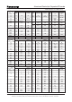
0.3 max
fD±0.5
B~G=L±0.3
H~K=L±0.5
(P) (I)
(I)
D L A,B H max. I W P K
Size
code
-0.20 to +0.15
±0.20
±0.20
-0.20 to +0.15
-0.20 to +0.15
-0.20 to +0.15
B
C
D
D8
E
F
G
H13
J16
K16
-0.20 to +0.15
±0.30
±0.30
±0.30
W.V. code
A± 0.2
w
B± 0.2
4.0
5.0
6.3
6.3
8.0
8.0
10.0
12.5
16.0
18.0
5.8
5.8
5.8
7.7
6.2
10.2
10.2
13.5
16.5
16.5
4.3
5.3
6.6
6.6
8.3
8.3
10.3
13.5
17.0
19.0
5.5
6.5
7.8
7.8
9.5
10.0
12.0
15.0
19.0
21.0
1.8
2.2
2.6
2.6
3.4
3.4
3.5
4.7
5.5
6.7
0.65±0.1
0.65±0.1
0.65±0.1
0.65±0.1
0.65±0.1
0.90±0.2
0.90±0.2
0.90±0.3
1.20±0.3
1.20±0.3
1.0
1.5
1.8
1.8
2.2
3.1
4.6
4.4
6.7
6.7
0.35
0.35
0.35
0.35
0.35
0.70
0.70
0.70
0.70
0.70
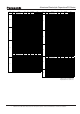
FK
V
Series:
Type :
=
Country of Origin
>
=
Endurance
tan d
DC leakage current
initial specified value
Shelf Life
Capacitance change
DC leakage current
After storage for 1000hours at +105±2 °C with no voltage applied and then being stabilized
at +20°C, capacitors shall meet the limits specified in Endurance.(With voltage treatment)
Resistance to
Soldering Heat
±10% of initial measured value
initial specified value
initial specified value
<
=
<
=
<
=
<
=
(µF)
C FK
10
W.V. code
Capacitance
Series
identification
Lot number
Negative polarity
marking
V 50 63 80 100
Code H J K 2A
V 6.3 10 16 25 35
Code j A C E V
FK
(
>
f12.5)
=
W.V. code
(µF)
Capacitance
Lot number
Series
identification
Negative polarity
marking
±30% of initial measured value (Suffix “G” is 35%)
200 % of initial specified value (Suffix “G” is 300%)
“G” in dia.8 to 10mm are 5000 hours)the capacitors shall meet the limits specified below.
After reflow soldering ( Refer to the "Application Guide" for recommended temperature profile.)
Capacitance change
and then being stabilized at +20°C, capacitor shall meet the following limits.
D.F. tan d
Aluminum Electrolytic Capacitor/FK series
Design and specifi cations are subject to change without notice. Ask factory for technical specifi cations before purchase and/or use.
Whenever a doubt about safety arises from this product, please contact us immediately for technical consultation.