
Datasheet


Light Touch Switches/EVQP6/6P6/7P6/9P6
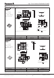
0.3 mm max.
Without Push Plate
With Push Plate
Switch
Mounting surface
Test pole
Leaning angle range
90 °±4 °
(
vertical direction
)
φ1.5
1.3
R0.1±0.05
Slant 0.3 mm max.
Without Push Plate With Push Plate
R0.1±0.05
R0.1±0.05
φ0.8
180
260
MAX.
150
230
90±30 40±10
(Normal Temp.)
Operation Top (°C)
Soldering Time (s)
Fan or Normal Temp.
■ Recommended Operating Conditions
■ Recommended Shape of Test Pole
■ Recommended Reflow Soldering Conditions
P
2
P
0
P
1
t
2
t
1
φD
0
A
B
Feeding hole
Chip component
Tape running direction
Chip pocket
F
W
E
Tape width=12.0 mm
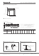
● Embossed Carrier Taping
Unit: mm
Part No.
Height ABWFEP
1
P
2
P
0
D
0
Dia. t
1
t
2
EVQP6
0.35/0.58
4.0±0.2 5.0±0.2 12.0
+0.3
5.5±0.1 1.75±0.10 8.0±0.1 2.0±0.1 4.0±0.1 1.5
+0.1
0.30±0.05 0.5/0.7
+0.2
EVQ6P6
EVQ7P6
EVQ9P6
0.43
–0
–0.1
–0.1
Designandspecificationsareeachsubjecttochangewithoutnotice.Askfactoryforthecurrenttechnicalspecificationsbeforepurchaseand/oruse.
Shouldasafetyconcernariseregardingthisproduct,pleasebesuretocontactusimmediately.
ANCTB10E 201709-Fd
Panasonic Corporation 2017
Panasonic Corporation
Electromechanical Control Business Division
–4–
industrial.panasonic.com/ac/e/
Taping condition : Lack of products in the middle of taping should be
one MAX, but total quantity specified in the
specifications should be secured.
Peeling off strength of top tape : It should be within 0.2N to 1.0N at
165 degree in peeling off angle.
Joint of carrier tape : One joint per one reel may exist.
cs6ANCTB10104.indd4 17/10/059:06