Ultra-minute Photoelectric Sensor EX-Z Series USER’S MANUAL WUME-EXZ-1 2015.4 panasonic.
Contens 1. Cautions···························································································3 2. Part Description·················································································4 3.
1. Cautions WARNING ●● Never use this product as a sensing device for personnel protection. ●● When using sensing devices for personnel protection, use products that meet laws and standards, such as OSHA, ANSI or IEC etc., for personnel protection applicable in each region or country. ●● This product has been developed / produced for industrial use only. ●● This product employs a small cable of 0.1mm2 in conductor area.
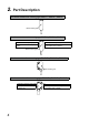
2. Part Description Thru-beam emitter side sensing type EX-Z11□, EX-Z12□, EX-Z13□ Beam emitting part Thru-beam receiver side sensing type EX-Z11□, EX-Z12□, EX-Z13□ Operation indicator (Orange) Lights up when the sensing output is ON.
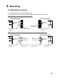
3. Mounting 3-1 Mounting of sensor ●● The tightening torque should be 0.2N·m or less. ●● M2 screw and nut, spring washer, and flat washer are accessory of this product. When tapping in mounting section (Unit: mm) 8.5 Sensing direction Sensing direction 8.5 M2×0.4 Tapping depth: 7 M2 screw (length 10) (accessory) M2×0.
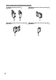
When using sensor mounting bracket (optional) 6 L-shaped mounting bracket MS-EXZ-1 Mounting bracket for front sensing type MS-EXZ-2 Mounting bracket for side sensing type MS-EXZ-3 Mounting spacer for front sensing type MS-EXZ-4
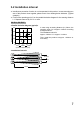
3-2 Installation interval ●● Interference prevention function is not incorporated in this product. In case mounting two sets of this product close together, please mount it as drawing below indicates. (Typical example) ●● Find out the operating point ℓ1 on the parallel deviation diagram for the sensing distance L1. Separate sensors by 2 X ℓ1 or more.
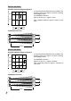
EX-Z12□, EX-Z12F□ Sensing distance L (mm) 200 100 In case using at sensing distance (L2) 200mm, the operation point (ℓ2) is approx. 30.5mm according to the diagram at left. The installation interval is Approx. 30.5mm X 2 = approx. 61mm Thus, install the product to approx. 61mm or more away.
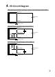
4.
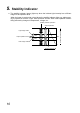
5. Stability Indicator ●● The stability indicator (green) lights up when the incident light intensity has sufficient margin to the operation level. When the beam is received at a level where the stability indicator lights up, stable sensing is possible in both the "Light" state operation and the "Dark" state operation without being affected by changes in temperature, voltage, etc.
6. Beam Alignment 1. Place the emitter and the receiver face to face along a straight line. Move the emitter in the up, down, left and right directions, in order to determine the range of the light received condition with the help of the operation indicator (orange), and place it almost at the center. Sensing object 2. Similarly, adjust for up, down, left and right angular movement of the emitter. Emitter 3. Further, perform the angular adjustment for the receiver also. 4.
7. Option 7-1 Sensor mounting bracket Product name Model No.
8. Specifications 8-1 Side sensing type Type Model No. NPN output (note 2) PNP output Sensing distance 50mm type Sensing distance 200mm type Sensing distance 500mm type Light-ON Dark-ON Light-ON Dark-ON Light-ON Dark-ON EX-Z11A EX-Z11B EX-Z12A EX-Z12B EX-Z13A EX-Z13B EX-Z11A-P EX-Z11B-P EX-Z12A-P EX-Z12B-P EX-Z13A-P EX-Z13B-P Sensing distance 50mm 200mm 500mm Minimum sensing object ø0.
8-2 Front sensing type Type Sensing distance 50mm type Light-ON Dark-ON Sensing distance 200mm type Sensing distance 500mm type Light-ON Dark-ON Light-ON Dark-ON EX-Z11FB EX-Z12FA EX-Z12FB EX-Z13FA EX-Z13FB Model No. NPN output EX-Z11FA (Note 2) PNP output EX-Z11FA-P EX-Z11FB-P EX-Z12FA-P EX-Z12FB-P EX-Z13FA-P EX-Z13FB-P Sensing distance 50mm 200mm 500mm Minimum sensing object ø0.3mm opaque object (Completely beam interrupted object) (Setting distance between emitter and receiver: 50mm) ø0.
9. Dimensions Thru-beam type side sensing type EX-Z11□, EX-Z12□, EX-Z13□ (Unit: mm) 6.5 6.5 3.5 1 12 8.5 4.25 0.4 3.5 1 12 8.5 0.4 4.25 1.75 2.2 1.75 2.2 2-ø2.2 2.5 2.9 4.25 5.5 2.9 2-ø2.2 2.5 5.5 4.25 ø2 cable 2m long [Cable diameter: ø0.6 (Note 1)] ø2 cable, 2m [Cable diameter: ø0.6 (Note 1)] Note: The cable diameter of inflection resistant cable type is ø0.7mm. Thru-beam type front sensing type EX-Z11F□, EX-Z12F□, EX-Z13F□ (Unit: mm) 1.75 2-ø2.2 2-ø2.
Sensor mounting bracket MS-EXZ-1 10.5 7 8 15 12 8.5 1.4 1.2 (Unit: mm) 3.2 4-M2 X 0.4 thru-hole threads 1.75 4.75 6.8 8.5 Sensor mounting bracket MS-EXZ-2 3.3 18.7 (Unit: mm) 1.2 9 1.4 3.2 6.25 3.2 4-M2 X 0.4 thru-hole threads 3.5 6.8 1.4 8 15 12 8.5 1.75 Sensor mounting bracket MS-EXZ-3 17.7 (Unit: mm) 1.2 7.25 7.5 9.9 1.4 1.4 15 8 8.5 12 3.2 3.5 16 3.2 6.8 2-M2 X 0.
Spacer for mounting at the back MS-EXZ-4 (Unit: mm) 5.1 8.5 12 2-ø2.2 2.8 1.7 3.5 4.
Please contact .......... ■ Overseas Sales Division (Head Office): 2431-1 Ushiyama-cho, Kasugai-shi, Aichi, 486-0901, Japan ■ Telephone: +81-568-33-7861 ■ Facsimile: +81-568-33-8591 panasonic.net/id/pidsx/global For sales network, please visit our website. © Panasonic Industrial Devices SUNX Co., Ltd.