
Datasheet
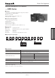

Plastic Film Capacitors
D
esign, Specifications are subject to change without notice. Ask factory for technical specifications before purchase and/or use.
Whenever a doubt about safety arises from this product, please inform us immediately for technical consultation without fail.
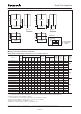
■Permissible Conditions
●Permissible Voltage
・These capacitors are designed only for DC voltage, so should not be used for AC line.
・Use the peak voltage (V
o-p
) within the rated voltage.
・Use the peak to peak voltage (V
p-p
) within 0.2 x V
R
.
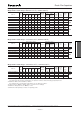
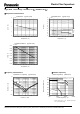
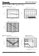
●DC Voltage, Peak current and RMS current derating
Derating of voltage (V
o-p
), RMS current (A
rms
), and peak current (A
o-p
) according to the following diagram
when the temperature of the capacitor surface exceeds 70 ℃.
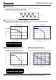
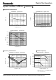
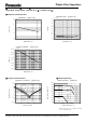
●Permissible self heating temperature rise ●Total cycles applied peak current
60 65 70 75 80 85 90 95 100
Voltage ①
Voltage ②
60 65 70 75 80 85 90 95 100
Voltage ①
Voltage ②
Permissible voltage (V
o-p
)
Temperature of capacitor surface T
C
(℃)
DC Voltage derating
Percentage to the permissible current (%)
Current derating
Temperature of capacitor surface T
C
(℃)
Total cycles applied peak current (A
o-p
)
(including pulse current) are within following diagram.
Permissible self heating temperature rise is
within following diagram when the temperature
of the capacitor surface exceeds 70 ℃.
Please consult Panasonic if your condition exceeds the above spec.
V
p-p
= 0.2 × V
R
V
R
≧ V
o-p
V
o
0%
20%
40%
60%
80%
100%
120%
60 65 70 75 80 85 90 95 100
Part Numb er Vo ltag e
①
Voltage
②
EZPE 50
□□□□
TA DC500V DC450 V
EZPE 80
□□□□
TA DC800V DC700 V
EZPE 1B
□□□□
TA
DC1100 V DC920 V
EZPE 1D
□□□□
TA DC1300V DC1100V
Tot a l c y c l e s
Percentage to the permissible peak current (%)
Permissible self temp. rise(℃)
Temperature of capacitor surface T
C
(℃)
0%
20%
40%
60%
80%
100%
120%
60 65 70 75 80 85 90 95 100
0%
20%
40%
60%
80%
100%
10 100 1000 10000 100000
Part Numb er 100% a t70
℃
36% at85
℃
EZPE50
□□□□
TA 12
℃
4.3
℃
EZPE80
□□□□
TA 10
℃
3.6
℃
EZPE1B
□□□□
TA 5
℃
1.8
℃
EZPE1D
□□□□
TA 9
℃
3.2
℃