Panasonic INSTALLATION INSTRUCTIONS Ventilating Fan Model No. Contents FV-08-11VFM5 F-08-11VF5 GENERAL SAFETY INFORMATION DESCRIPTION -cerement UNPACKING omen SUPPLIED ACCESSORIES DIMENSIONS FEATURE FV-08-11VF5 READ AND SAVE THESE INSTRUCTIONS Thank you for purchasing this Panasonic product.
GENERAL SAFETY INFORMATION For Your Safety To reduce the risk of injury, loss of life, electric shack, fire, malfunction, and damage to equipment or property, always observe the following safety precautions. Explanation of symbol word panels The following symbol word panels are used to classify and describe the level of hazard, injury, and property damage caused when the denotation is disregarded and improper use is performed.
GENERAL SAFETY INFORMATION CONTINUED A WARNING 0 These models are UL listed for tub and shower enclosures. © Canada only: Not to be installed in a ceiling thermally insulated to a value greater than R40. ® Do not disassemble the unit for reconstruction. It may cause fire or electric shock. A statement to the effect that when the product is to no longer be used, it must not be left in place but remove, to prevent it from possibly falling.
DESCRIPTION These Panasonic ventilating fan models are listed by UL under UL file No. E78414. These Panasonic ventilating fan models use a sirocco Blower driven by a capacitor motor. The motor is designed to have an extended service life with reduced energy consumption. It also incorporates a thermal-cutoff for safety. The grille covering the fan body is a spring-loaded, quick remove type. A damper for preventing air counter flow is provided.
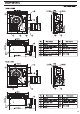
DIMENSIONS Unit: inches (mm) FV-08-11VFM5 012 1/8 (307) 1172 38) (29) 27/812) CTT 013 (330) No. Part name No. Part name Blade @ | Grille Pick-A-Flow switch Damper 5 : Ulf [3] Junction box (® | Flex-Z Fast™ bracket Adapter 40 | Adapter connector 338 (5 | Main PCB assembly Fan 010 1/4 (260) 6(150) | (® | sensor unit oO 1 FV-08-11VF5 012 178 (307) 112.68, 129 20) £ flo O13 (330) Part name No.
WIRING DIAGRAM FV-08-11VFM5 Fan body Junction box Red PCB Capacitor 1 White 1 [White], White| Neural _ om Fuse in motor) Switch Black | [110 CFM Power supply Yellow ST AC120V 60Hz x Fuse in in motor) 80 CFM Black Black | lve Black Blue Green .
INSTALLATION (NEW CONSTRUCTION) The fan position between joists from center can be adjusted flexibly. A CAUTION 0 Please wear gloves to protect hands during the installation as follow. 1. Remove the junction box and duct adapter from the fan housing before installing the fan. Remove the machine screw (M4X6) and disconnect the electrical mole cable by pinching the tabs to insure the junction box and adapter dear the fan housing when sliding the adapter off the housing. {Fig.
INSTALLATION (NEW CONSTRUCTION) CONTINUED 8. Insert fan body and slide into adapter assembly until the flange overlaps the Flex-Z Fast™ bracket. Secure the fan body to Flex-2 Fast™ bracket by using 2 self-drilling screws, plug connector to receptacle and secure the fan body to adapter by using machine screw (M4X6). {Fig.6) A CAUTION Secure the duct adapter to the fan housing with the machine screw (M4X6) by re-inserting and carefully screwing the adapter to the housing.
INSTALLATION (RETROFIT) A WARNING 0 Disconnect power source before working on unit. 1. Remove the existing fan and cut ceiling opening. Install the Flex-Z Fast™ bracket to joists by using the 4 per-installed tapping screws (ST4.2x20). Leave existing duct work and wiring in place. (Fig.12) 2. Follow the step page 7. (Before connect the circular exhaust duct to the adapter, pull down the circular duct from the ceiling.} 3. Install the adapter to Flex-Z Fast™ bracket by using 2 self-drilling screws. (Fig.
MAINTENANCE (CLEANING) A WARNING (1) Disconnect power source before working on unit. A CAUTION Routine maintenance must be done every year. Please wear gloves during the cleaning work. Never use gasoline, benzene, thinner or any other such chemicals for cleaning the ventilating fan. Do not immerse motor in water when cleaning. Do not soak resin parts in water over 140°F 1. Clean grille. {Don’t put into hot water. Use non-abrasive kitchen detergent, wipe dry with clean 2.
PRACTICAL GUIDE TO INSTALLATION Properly insulate the area around the fan to minimize building heat loss and gain. (Fig.18) Loose fill or bat insulation can be placed directly over the fan housing in the attic. Our fans and fan/light combination units do not create excessive heat that is a common problem with recessed light fixtures or some competitor's fan/light combination. Qur efficient, cool-running motors and our fluorescent lamps do not create enough ambient heat to be subjected to these limitations.
PRODUCT SERVICE Warning Conceding Removal of Covers. The unit should be serviced by qualified technicians only. Your product is designed and manufactured to ensure a minimum of maintenance. Should your unit require service or parts, call Panasonic Call Center at 1-866-292-7299 (USA) or 1-800-669-5165 (Canada). Panasonic Corporation of North America Two Riverfront Plaza, Newark, NJ 07102 WWww.panasonic.com Panasonic Canada Inc.