Ventilating Fan FV-08VSL1 READ AND SAVE THESE INSTRUCTIONS. R Please read these instructions carefully before attempting to install, operate or service the Panasonic Ventilating Fan. Failure to comply with instructions could result in personal injury and/or property damage. Please retain this booklet for future reference.
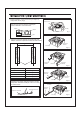
SUPPLIED ACCESSORIES FV-08VSL1 Part name Appearance Quantity Part name Screw III (ST4.2X16) Grille Quantity 2 1 Machine screw (M4X8) Suspension bracket I 1 Suspension bracket II 1 Suspension bracket III Appearance 1 Long screw (ST4.2X20) 6 Thumb screw 1 18W Fluorescent lamp 2 4W Night lamp 1 Lighting unit 1 1 Screw I (ST4.2X8) 2 Screw II (ST4.2X12) 2 DESCRIPTION The Panasonic ceiling mount ventilation fans uses a sirocco fan driven by a capacitor motor.
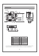
DIMENSIONS Unit: inches(mm) FV-08VSL1 12 2 7/8 (73) 2 3/8 (60) 6 5/16 (160) 9 7 1/2 (13) 1 (25) 1 1/2 (38) 13 1/4~15 1/2 ( 336~394 ) 16 1/2~18 3/4 ( 419~480 ) 21 1/4~23 1/2 ( 540~597 ) 3 1/8 (78) 12 (300) 10 1/4 (261) 3 (76) 5 17/32 (140) 13 (330) 8 3 1/8 (78) 11 3 6/8 (95) 10 13 (330) 6 10 1/4 (261) 3 3/4 (94) No. Part name No.
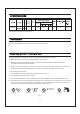
SPECIFICATIONS Duct Noise diameter (sones) (inches) FV-08VSL1 3 Lighting unit Fan body 1.3 26 18 X 2 4 (rpm) (cfm) 944 80 12.8 (5.8) Specifications are based on HVI standard. UNPACKING Unpack and carefully remove unit from carton. Refer to the Supplied Accessories list to verify that all parts are present. GENE R AL SAFETY INFO R MATION o o 1. Do not install this ventilating fan where air temperature may exceed 40 C (104 F). 2.
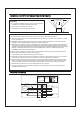
GENE R AL SAFETY INFO R MATION CONTINUED (Cooking area) Do not install above or inside this area CAUTION: 1. For general ventilating use only. Do not use to exhaust hazardous or explosive materials and vapors. o 45 o 45 2. Not for use in cooking area. (Fig .B) 3. This product must be properly grounded. Cooking equipment Floor Fig. B WARNING: To reduce the risk of fire, electric shock or injury to persons, observe the following: A. Use this unit only in the manner intended by the manufacturer.
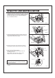
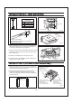
INSTALLATION I ( JOIST MOUNTING- I ) 1. Before installation, secure the fan body to adaptor by using thumb screw. (Fig.1) Thumb screw IMPORTANT : Remove the tape from damper and adaptor before installation. As shown below: Adaptor Fan body Damper Fig.1 Tape 2. Insert the suspension bracket into the fan body and adaptor. (select the suspension bracket as shown below) Suspension bracket I A Fan body Fig.2-1 Suspension bracket I Fan body Joists Suspension bracket III Fig.
INSTALLATION I ( JOIST MOUNTING- I ) CONTINUED 3. Install the suspension bracket and the flange of fan body to joists by using long screws (ST4.2X20) ( If spacing A between joists is 10 1/4~12 inches, install the flange of fan body according to Fig.3-2, others according to Fig.3-1 install the product.) Joist Fan body 4 Long screws (ST4.2X20) Fig.3-1 A = 10 1/4~12 inches Joist 2 Long screws (ST4.2X20) Fan body Fig.3-2 4. Install the suspension bracket to joists by using long screws (ST4.
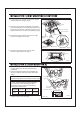
INSTALLATION I ( JOIST MOUNTING- I ) CONTINUED 8. Finish ceiling work. Ceiling hole should be aligned with the edge of the flange. (Fig.6) 12 5) 12 1/8 (30 1/8 (30 5) Ceiling 9. Insert the plug connector II and plug connector III into the receptacle II and receptacle III respectively, and secure the light unit to the fan unit with 2 screw III (ST4.2X16) and 1 machine screw (M4X8). (Fig.6) Plug connector II Plug connector III Lighting unit 10.
INSTALLATION II ( JOIST MOUNTING- II ) CONTINUED 4. Insert the suspension bracket into fan body (refering to step 2 of installation I, page 6). Circular duct Joist 5. Insert the fan body into joists. (Fig.9) IMPORTANT: Conduit Junction box cover Make sure that adaptor claws are properly inserted into body slots. 6. Secure the fan body to adaptor by using thumb screw and plug connector to receptacle. (Fig.10) 7. Secure the suspension bracket to joists by using long screws (ST4.
INSTALLATION III ( I - JOIST MOUNTING ) C 4 kind of I-joist inches (mm) 9/16 (14.3) C1 11/16 (17.5) C2 31/32 (24.6) C3 C4 1 17/32 (38.9) Fan body Thumb screw Fig.13 C3 C4 Suspension bracket III Screw II (ST4.2X12) C1 C2 Suspension bracket III The suspension bracket III can comply with different kinds of I-joist. Fig.14 1. Before installation, secure the fan body to adaptor by using thumb screw (Fig.13). Secure the lighting unit to fan body (refering to Fig.6 of page 8). 2.
INSTALLATION IV ( BETWEEN JOIST MOUNTING ) CONTINUED 3. Insert the fan body between joists. Make sure the fan body is level and square (perpendicular) with the joists. (Fig.17) Joists CAUTION: Backside of flange should mount directly to bottom of joist. Adaptor Fan body Junction box Suspension bracket 13 1/4~15 1/2 ( 336~394 ) 16 1/2~18 3/4 ( 419~480 ) 21 1/4~23 1/2 ( 540~597 ) A inches ( mm ) 4. Secure the suspension bracket to joists by using long screws (ST4.2X20). (Fig.18, Fig.19) Fig.
INSTALLATION V ( WOODEN HEADE R ) CONTINUED 4. Follow step 5 to 11 of installation I (page 7~page 8) to complete the installation work. Junction box Circular duct 6 Long screws (ST4.2X20) Conduit Junction box Wire nut Lead wires Green wires Fig.21 INSTALLATION VI ( IN EXISTING CONST RUCTION ) 1. Installation in existing construction.
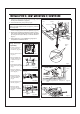
MAINTENANCE I (CLEANING) Slot WARNING: Disconnect power source before working on unit. Routine maintenance must be done every year. Mounting spring CAUTION: 1. Never use petrol, benzene, thinner or any other such chemicals for cleaning the ventilating fan. 2. Do not damp water to enter motor. o 3. Do not soak resin parts in water over 60 C. Gloves Grille Fig. 22 1. Remove grille. (Squeeze mounting spring and pull down carefully.) (Fig.22) 2. Wash and clean grille.
MAINTENANCE II (REPLACEMENT OF LAMP) CONTINUED 1. Remove grille. (Squeeze mounting spring and pull down) (Fig.22 of page 13) Plug connector II Plug connector III 2. Disconnect connector II or connector III from lighting unit. (Fig.26) Receptacle III Receptacle II Fluorescent lamps 4 W Night Lamp Fig.26 3. Change the fluorescent lamps (Panasonic FDS 18E27/4,18 W or FDS18E35/4, 18 W or FDS18E42/4, 18 W ) or the 4 W night lamp, connect the connector II or connector III and replace the grille. (Fig.
PANASONIC CONSUMER ELECTRONICS COMPANY Division of Panasonic Corporation of North America, One Panasonic Way, Secaucus, NJ 07094 PANASONIC CANADA INC. 5770 Ambler Driver, Mississauga, ON L4W 2T3 www.panasonic.