Ventilating Fan Model No. FV-11VH2 FV-11VH2 FV-11VHL2 FV-11VHL2 Thank you very much for having purchased our Ventilating Fan.
UNPACKING Unpack and carefully remove unit from carton. Refer to the Supplied Accessories list to verify that all parts are present. SUPPLIED ACCESSORIES FOR MODEL FV-11VH2 FOR MODEL FV-11VH2 POURLE MODELE FV-11VHL2 POURLE MODELE FV-11VHL2 DESCRIPTION The Panasonic ceiling mount ventilating fans uses a sirocco fan driven by a capacitor motor. The motor is designed to have an extended service life with reduced energy consumption. It also incorporates a thermal cut-off for safety.
7 5/8 (195) Ventilating unit 2 1/2 (62) 5 (128.7) 11 1/4 (285.5) 2 1/8 (54.8) 7 3/4 (196) 7 5/8 (195) 14 (357.8) 11 7/8 (301) 11 1/4 (285.5) 13 1/4 (337.8) 11 7/8 (301) 2 1/2 (62) 1 (25) 7 3/4 (196) DIMENSIONS 19 1/2 (497) 16 (407) 18 1/8 (460) 5 (128.
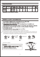
SPECIFICATIONS Noise Vent (0.1" WG) (cfm) Exhaust & Circulation 29.5 Vent (sone) 650 0.6 15.6 (7.1) 720 0.7 17.8 (8.1) 1540 GENERAL SAFETY INFORMATION AC 120V, 60Hz. 8. Make sure that all duct work is properly vented. 9. DO NOT INSTALL THIS UNIT OVER A BATHTUB OR SHOWER ENCLOSURE. 10. This product (FV-11VHL2) has a fluorescent lamp that contains mercury. Disposal may be regulated in your community due to environmental considerations.
GENERAL SAFETY INFORMATION CONTINUED WARNING: To reduce the risk of fire, electric shock or injury to persons, observe the following: A. Use this unit only in the manner intended by the manufacturer. If you have any questions, please contact the manufacturer. B. Installation work and electrical wiring must be done by qualified person(s) in accordance with all applicable codes and standards, including fire-rated construction. Neither unauthorized modification, repair nor disassembly is allowed. C.
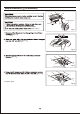
INSTALLATION (JOIST MOUNTING- ) Illustrations in this manual common use the image of FV-11VHL2, and mark for FV-11VHL2 only, others are same for FV-11VH2. 1. Before installation, remove warning lable and the tape that is securing the adapter and the damper. (Fig.1) Warning label Suspension bracket Fan body Suspension bracket Tape Suspension bracket Fan body Fig.2-1 Suspension bracket Fig.1 2. Insert the suspension bracket into the fan body. (Select the suspension bracket as shown below.
INSTALLATION (JOIST MOUNTING- ) CONTINUED 5. Remove the lighting cord out from hook (FV-11VHL2), then remove junction box plate and secure conduit or stress relief to wiring box knock-out hole.(Fig.5) 6. Refer to wiring diagram (Page.5) Follow all the local electrical safety codes. As well as the National Electrical Code (NEC). Using UL approved wire nuts, connect house power wires to ventilating fan wires (Fig.6): Black to black; white to white; green to green.
INSTALLATION (BETWEEN JOIST MOUNTING) Illustrations in this manual common use the image of FV-11VHL2. 1. Before installation, remove warning lable and the tape that is securing the adapter and the damper. (Fig.1) Fig.11 (Select the suspension bracket according to spacing A as shown below.) Suspension bracket Fan body Suspension bracket Suspension bracket B Fig.11 Joists B Spacing A on center joists 16 inches 13 1/4 ~ 15 1/2 (336~394) 19.2 inches horizontal joists 14 3/4 ~ 16 3/4 (374~425) 19.
INSTALLATION (BETWEEN JOIST MOUNTING) CONTINUED Fig.13, Fig.14 Joist 2 Long screws (ST4.2X20) Fig.13 2-Screw (ST4.2X12) Fig.14 4 Long screws (ST4.2X20) Joist 6. Follow step 5 of installation installation work. (page 7) to complete the Fig.14 INSTALLATION (WOODEN HEADER INSTALLATION) 1. Before installation, remove warning lable and the tape that is securing the adapter and the damper. (Fig.1) Ceiling joist 11 3 /8 ( Header Ceiling joist 290 ) /8 19 7 (505 ) Adaptor (Fig.15, Fig.
MAINTENANCE (CLEANING) Slot Mounting spring Gloves Grille Do not allow any water to get into the motor. 60 oC(140 oF). 1 1 2 Fig.17 Fig.17 Fig.18 Fig.18 Fig.19 Vacuum cleaner Fig.19 Fig.20 5. Replace grille. Fig.
MAINTENANCE (REPLACEMENT OF LAMP) 4. Be sure to remove the night lamp before removing fluorescent lamps. (Fig.17 of page 10) 2. Remove the 4 W night lamp.(Fig.21) Night lamp Fluorescent lamp Fig.21 3. Change the fluorescent lamps (FDS18E35/4, 18 W) (Fig.22) or the 4 W night lamp(Fig.21), replace the grille. Fluorescent lamp Fig.
PRACTICAL GUIDE TO INSTALLATION Properly insulate the area around the fan to Fig.23 Dryer-hood type vent with backdraft flap (s). Caulk termination to duct. 2-3 ft straight run before elbow. In attic installation, caulk box to drywall. Short piece of flexible duct helps alignment and absorbs sound. Use clamps plus tape at all flex joints. Insulation Foil tape tightly covers all metal duct joints (glue PVC joints). Fig.