FV-08VQL6 FV-15VQL6 FV-11VQL6 2-3 5 5 6-8 FV-08VQL6 FV-11VQL6 11 Back cover Back cover Back cover FV-15VQL6 Thank you for purchasing this Panasonic product.
For Your Safety To reduce the risk of injury, loss of life, electric shock, fire, malfunction, and damage to equipment or pro always observe the following safety precautions. Explanation of symbol word panels The following symbol word panels are used to classify and describe the level of hazard, injury, and property damage caused when the denotation is disregarded and improper use is performed. WARNING Denotes a potential hazard that could result in serious injury or death.
WARNING USA only: This product has two fluorescent lamps that contain mercury. Disposal may be regulated in your community due to environmental considerations. For disposal or recycling information, please contact your local authorities or visit Panasonic website: http://www.panasonic.com/environmental or call 1-888-769-0149. Canada only: Not to be installed in a ceiling thermally insulated to a value greater than R40. Do not disassemble the unit for reconstruction. It may cause fire or electric shock.
The lighting unit is an energy-saving, lighting device that uses two 13W fluorescent lamps and produces almost the same illumination as a standard 100W incandescent lamp. FCC Note: This equipment contains two self-ballast fluorescent lamp and is in compliance with Part 18 of the FCC Rules as consumer RF lighting device. These limits are designed to provide reasonable protection against harmful interference in a residential installation.
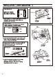
4 3/5 (116) FV-08VQL6 FV-11VQL6 10 1/4 (260) 4 3/5 (116) FV-15VQL6 10 1/4 (260) Wiring diagram Junction box Fan body Fluorescent lamp (Self-ballasted) Night lamp Black Live White Neutral Black Live White (Fuse in motor) Fuse type: FV-08VQL6: (114 FV-11VQL6: (114 FV-15VQL6: (134 c ) Impedance - protected c ) Impedance - protected c ) Thermally protected (N.LIGHT) (Power supply) AC120V 60Hz Capacitor Motor (LIGHT) Neutral Black Live Green (Earth ground) (VENT.
Fig.1 Fig.
6. Refer to wiring diagram. (Wiring detail please refer to the wiring diagram on page 5.) Fig.3 CAUTION (Night lamp) Fig.4 Fig.5 8. Remove screw (M4X8). Remove light cover. (Fig.6) Fig.
9. Install the night lamp and fluorescent lamps. (Fig.7) 3 Fig.7 10. Install light cover. (Fig.8) Secure screw (M4X8) Fig.8 CAUTION (Fig.9) 11. (Fig.9) 12. (Fig.9, Fig.10) CAUTION Fig.9 Fig.
Fig.11 (Fig.11, Fig.12) (Fig.13) Fig.12 12 (page 7, page 8) Fig.
(Fig.14) 12 (page 7, page 8) Fig.14 WARNING CAUTION Fig.15 1.Clean grille. (Don’t put into hot water. Use non-abrasive kitchen detergent, wipe dry with clean cloth) (Fig.15) Fig.16 (Fig.16) (Fig.17) Fig.
WARNING ‘ Fig.18 CAUTION Remove dust and dirt from light cover and lens, before replace the lamps. (Fig.18) Fig.19. Fig.19 . Fig.19 Lens 3. Replace the fluorescent lamps (Maxlite MLS13GU35 13W) as shown in step 1 and step 2 of Fig.20. 4. Replace the 4W night lamp. (Fig. 20) Install the fluorescent lamps (Maxlite MLS13GU35 13W) as shown in step 2 and step 3 of Fig.7 (page 8). 5. Install light cover. (Fig.8 of page 8) 3 Fig.
(Fig.21) Fig.21 FV-08VQL6 26 10.6 (4.8) FV-11VQL6 26 10.6 (4.8) FV-15VQL6 26 11.9 (5.