
Installation Manual


6
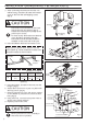
3. After confirming the direction that the unit
will be facing, attach the bracket and bracket
cover to the unit with self-tapping screws.
(Fig.2)
CAUTION
The holder was assembled on the back
side of the unit. (no shown in Fig.2)
Attach the unit body horizontally to the
panel of your choice.
For best results, the bracket and bracket
cover should be attached vertically.
The holder and the bracket should be
installed on the same side of the joist.
4. Insert installation bracket into bracket cover.
If joist space is greater than distance B at the
center (table 2), attach installation bracket and
extension bracket as shown below.
Installation
bracket
Extension
bracket
Short
screw
Dimension: mm(inch)
MODEL FV-10NLF1E FV-20NLF1 FV-30NLF1 FV-40NLF1
B
381
(15)
421
(16
1
2
)
461
(18
1
8
)
461
(18
1
8
)
(table 2)
5. Insert the holder, located on the unit, into the
hanger. (Fig.3)
6. Attach the In-Line Fan to a joist or a pillar with
the long screws. (Fig.4)
7. Remove junction box cover and secure conduit
or wire holder to junction box cover knockout
hole. (Fig.5)
8. Using wire nuts, connect house power wire as
shown in the wiring diagram.
9. Replace junction box cover.
CAUTION
Mount junction box cover carefully so
that wires are not pinched.
Fig. 2
Self-tapping
screws
Bracket
Bracket
cover
Fig.4
Circular duct
Ceilling
joist
Conduit
Long
Screw
Long
Screw
Green wire
Cord clip
Junction box
Red wire
Blue wire
Condenser
White
Black
Conduit
Wire nut
Junction box cover
Fig.5
INSTALLATION I (HORIZONTALLY BETWEEN JOISTS)
Fig. 3
B