
Datasheet

159
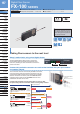
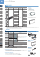
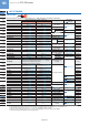
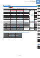
Digital Fiber Sensor FX-100 SERIES
FIBER
SENSORS
LASER
SENSORS
PHOTOELECTRIC
SENSORS
MICRO
PHOTOELECTRIC
SENSORS
AREA
SENSORS
LIGHT
CURTAINS
PRESSURE /
FLOW
SENSORS
INDUCTIVE
PROXIMITY
SENSORS
PARTICULAR
USE SENSORS
SENSOR
OPTIONS
SIMPLE
WIRE-SAVING
UNITS
WIRE-SAVING
SYSTEMS
MEASUREMENT
SENSORS
STATIC CONTROL
DEVICES
ENDOSCOPE
LASER
MARKERS
PLC /
TERMINALS
HUMAN MACHINE
INTERFACES
ENERGY CONSUMPTION
VISUALIZATION
COMPONENTS
FA COMPONENTS
MACHINE VISION
SYSTEMS
UV CURING
SYSTEMS
Selection
Guide
Fibers
FX-500
FX-100
FX-300
FX-410
FX-311
FX-301-F7/
FX-301-F
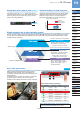
SET mode
SET mode
Simply press the ON button when an object is present
and OFF when it is not. There is no need to switch
settings or make judgments between Light-ON (
)
and Dark-ON (
).
Thru-beam type / Retroreflective type
<Setting example>
Reflective type
Object absent OFF
Object present ON
Object present ON
Object absent OFF
n
This carries out teaching and sets threshold values only
when no object is present (when the incident light amount
is stable). This is useful when sensing objects if there
are other objects in the background and when sensing
minute objects. Teaching can also be carried out using
external input.
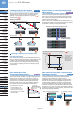
PRO mode
PRO mode
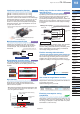
Variations in the amount of light received
Unify at 500 using
the GETA function
This function seeks changes in the light emitting amount
resulting from changes in the environment over long
periods (such as dust levels), so that the incident light
intensity can be checked at desired intervals and the
threshold values can be reset automatically. Reduces
the number of man-hours needed for maintenance.
Time
Current value
The amount of light
received when there
is no object
Incident light intensity
Threshold value
* Becomes active when the
output operation is set
to on, the beams are not
received, and when using
semi-transparent or mirrored
Even when performing the same sensing operation,
amp. There is no problem with the sensor itself, but the
Given value can be corrected with the GETA function, so
the apparent variation can be eliminated and the creation
of operation manuals can proceed smoothly.
4,000
500
0
500
1,000
0
[digits]
current value
4,000
[digits]
Correcting an incident light intensity display of ‘ ’ to
Not
displayed
Incident light intensity
Because the original
value is 500, the
displays for the lower
limit value will be 500
and the upper limit
value will be 4,000.
display as ‘ ’
If the light receiving level becomes saturated when
sensing over short distances or when sensing
transparent objects or minute objects, the light emitting
amount can be reduced so that stable sensing can be
provided without needing to change the response time.
On previous models, there was only one light reduction
level, but now there are 3 levels plus an automatic mode.
needed to be altered for proper sensing, this function can
allow simple settings alterations.
Light emitting
amount changed
A
,
B
,
A
4000
B
Upper display limit
Saturated digit
difference: D
Actual digit difference: C
【Light receiving level saturated】【Stable sensing】
Actual digit difference: C
Incident light
intensity
Incident light
intensity
03/01/2012