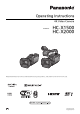
Operating Instructions 4K Video Camera Model No. HC- X1500 HC- X2000 Please read these instructions carefully before using this product, and save this manual for future use.
Information for Your Safety Information for Your Safety For the AC mains plug of three pins Before use ∫ Caution for AC mains lead Remove the connector cover. For your safety, please read the following text carefully. How to replace the fuse This appliance is supplied with a moulded three pin mains plug for your safety and convenience. A 5-ampere fuse is fitted in this plug.
Information for Your Safety ∫ Disposal of Old Equipment and Batteries Only for European Union and countries with recycling systems These symbols on the products, packaging, and/or accompanying documents mean that used electrical and electronic products and batteries must not be mixed with general household waste. For proper treatment, recovery and recycling of old products and used batteries, please take them to applicable collection points in accordance with your national legislation.
Information for Your Safety ∫ Cautions for use Keep this unit as far away as possible from electromagnetic equipment (such as microwave ovens, TVs, video games etc.). ≥ If you use this unit on top of or near a TV, the pictures and/or sound on this unit may be disrupted by electromagnetic wave radiation. ≥ Do not use this unit near cell phones because doing so may result in noise adversely affecting the pictures and/or sound.
Trademark ≥ SDXC logo is a trademark of SD-3C, LLC. ≥ “AVCHD”, “AVCHD Progressive” and the “AVCHD Progressive” logo are trademarks of Panasonic Corporation and Sony Corporation. ≥ Manufactured under license from Dolby Laboratories. Dolby, Dolby Audio, and the double-D symbol are trademarks of Dolby Laboratories. ≥ The terms HDMI and HDMI High-Definition Multimedia Interface, and the HDMI Logo are trademarks or registered trademarks of HDMI Licensing Administrator, Inc.
∫ Conventions used in this manual ≥ Words and phrases in [ ] brackets indicate content displayed in the LCD monitor. ≥ Words and phrases in < > brackets indicate design text used on this unit, such as button names. ∫ Reference pages ≥ Reference pages in this document are indicated by (l 00). ∫ Terminology ≥ The battery pack is described as “battery”. ≥ SDHC memory card, and SDXC memory card are referred to as “SD card” or “memory card” unless distinguished otherwise.
Contents Contents Information for Your Safety.............................................................2 Chapter 1 Overview Menu settings................................................................................. 61 [THUMBNAIL] menu .........................................................................61 [CAMERA] menu ..............................................................................62 [SCENE FILE] menu.........................................................................
Contents Convenient shooting functions ..................................................131 Zebra patterns display ................................................................... 131 Displaying the marker .................................................................... 131 Focus assist function ..................................................................... 132 Face detection/tracking AE&AF function ....................................... 135 Optical image stabilizer function ................
Chapter 1 Overview Before using the unit, read this chapter.
Chapter 1 Overview — Before using the unit Before using the unit ∫ Before using the unit, always check if the built-in battery is not consumed, and then set the date/time. The date of the internal clock of the unit resets to January 1, 2020 if the built-in battery is exhausted. This may result in the meta data of the clip not being recorded correctly, and it may not display correctly in the thumbnail screen. Connect the AC adaptor to the main unit or attach a battery when recharging the built-in battery.
Chapter 1 Overview — Before using the unit ∫ Do not apply insecticide or volatile material to the camera. ≥ The main unit may deform or the paint may peel off when insecticide or volatile material is applied. ∫ Do not allow the camera to remain in contact with a rubber or vinyl object for a long period of time. ∫ Disconnect the battery or disconnect the AC cable from the power outlet after the use. ∫ Battery characteristics The battery is a rechargeable lithium-ion battery.
Chapter 1 Overview — Before using the unit ∫ Exemption of liability Panasonic is not liable in any way regarding following. 1 Incidental, special, or consequential damages caused directly or indirectly by the unit 2 3 4 Damages, breakage of the unit, etc.
Chapter 1 Overview — Accessories/Optional accessories Accessories/Optional accessories Accessories Check the accessories before using this unit. Product numbers correct as of January 2020. These may be subject to change. Battery pack (l 25) AG-VBR59 Eye cup (l 29) DVZE1040Z AC adaptor (l 26) SAE0011A ∫ For the X2000 The following accessories are also supplied. Handle unit (l 30) VW-HU1 ≥To purchase as a supplied accessory, use part number 1KC1VWHU1EK when ordering.
Chapter 1 Overview — When turning on the power for the first time When turning on the power for the first time The time zone, date, and time are not set when the unit is shipped. [TIME ZONE] is displayed in the LCD monitor when the power is turned on for the first time. Follow the guidance and make the settings in the order of [TIME ZONE] and then [CLOCK SETTING]. ≥ You can do these operations either with the multidial or by touching the LCD monitor.
Chapter 1 Overview — What you can do with this unit What you can do with this unit Recording to the memory card Recording in following types is possible. ≥ MOV recording (UHD and FHD recording) ≥ MP4 recording (UHD and FHD recording) ≥ AVCHD recording ≥ Simultaneous recording ≥ Relay recording ≥ Interval recording ≥ Background recording ≥ Pre-recording Linking to external devices Connecting to TV/monitor Connect to a TV/monitor and output images.
Chapter 1 Overview — What you can do with this unit Connecting to the network This unit is equipped with wireless LAN. It can connect to wireless LAN devices via a network. Available functions When the unit is connected to a network, the following functions are available. ∫ Connecting to HC ROP app You can remotely control this unit with the HC ROP app by connecting this unit with an iPhone/iPad or Android terminal via wireless LAN.
Chapter 2 Description of Parts This chapter describes the names, functions, and operations of parts on the unit.
Chapter 2 Description of Parts — Main unit Main unit The illustrations in this document show the handle unit ( X2000 supplied, X1500 optional) removed. 8 7 9 10 1 23 18 19 4 5 6 20 11 12 13 14 15 16 17 21 22 23 30 29 28 27 26 25 24 1 2 Lens hood (l 28) 3 Focus ring (l 108) When the button is pressed to set to manual focus mode ([MF]) you can focus manually.
Chapter 2 Description of Parts — Main unit 25 button (l 109) 29 button Switches the shutter mode. Returns to one level higher when the menu is displayed. Pressing the button without confirming the setting value will not reflect the change in the setting. 26 button (l 106) Selects the method for adjusting screen brightness. 30 Multidial (l 140) 27 button (l 105) Moves, selects, and sets the menu while the menu is displayed.
Chapter 2 Description of Parts — Main unit X2000 42 43 44 45 46 51 47 52 48 49 50 42 Status indicator (l 34) 48 Headphones terminal Illuminates when power is on. Connects audio monitoring headphones. 43 Battery release lever (l 25) 49 Charging lamp (l 26) Used when removing the battery from the main unit. Illuminates when the battery is charging. 44 Battery mounting section (l 25) 50 terminal (l 26) Attaches a battery.
Chapter 2 Description of Parts — Handle unit ([X2000] supplied, [X1500] optional: VW-HU1) Handle unit ([X2000] supplied, [X1500] optional: VW-HU1) 1 2 3 4 7 6 8 9 10 15 14 13 5 11 12 16 A With a microphone holder attached 1 2 Handle 3 Microphone holder (l 30, 32) Secures the external microphone in place. 4 Buckle (l 30, 32) Used to open and close the microphone holder. 11 switch (l 123) 12
Chapter 2 Description of Parts — Handle unit ([X2000] supplied, [X1500] optional: VW-HU1) 17 18 19 20 21 22 23 26 25 17 Light cover ≥ Keep the Light cover out of reach of children to prevent swallowing. 18 Built-in LED light (l 117) 19 Tally lamp (l 52) Illuminates when the recording is started. Flashes when the battery level becomes low. Whether or not to illuminate the lamp can be set in the menu. 20 Accessory shoe (on the handle) Attach a video light, etc.
Chapter 2 Description of Parts — Basic operation Basic operation Multidial operation Operate the multidial on the main unit by turning it in vertical direction or pushing it. ≥ Turning the multidial in vertical direction will move the cursor. ≥ Pressing the multidial will select or confirm the item with cursor. ≥ Values of the menu or the pages of the thumbnail screen can be changed continuously by pressing and turning the multidial vertically to fix the setting.
Chapter 3 Preparation Before you use the unit, attach the battery following the procedures in this chapter. The attaching of accessories is also described in this chapter.
Chapter 3 Preparation — Power supply Power supply A battery or the supplied AC adaptor can be used as the power supply for the unit. ≥ The unit is compatible to following batteries. (As of January 2020) j AG-VBR59 (supplied/optional, supports quick charging) j VW-VBD58 (optional) ≥ AG-VBR59 supports quick charging. Use a battery charger (AG-BRD50: optional) to perform quick charging. Attaching and removing the battery ¥ Press the power button to turn off the unit.
Chapter 3 Preparation — Power supply Charging the battery The battery is not charged at the time of purchase. Use only after charging sufficiently. It is recommended that you have one extra battery. ≥ It is recommended to perform charging of the battery in a location with ambient temperature of 10 °C to 30 °C (same for the battery temperature). ≥ Use the supplied AC adaptor. Do not use the AC adaptor of another device. ≥ The supplied AC cable is dedicated for this unit. Do not use with any other device.
Chapter 3 Preparation — Power supply Standard charging time and recordable time Battery parts number Voltage/capacity (minimum) Charging time for main unit [FREQUENCY] AG-VBR59 (supplied/optional) 7.28 V/5900 mAh Approx. 5 h 30 min [59.94Hz] VW-VBD58 (optional) 7.2 V/5800 mAh Approx. 5 h 15 min [50.00Hz] Continuous recordable time X1500 X2000 Approx. 5 h 20 min Approx. 4 h 35 min [50.00Hz] Approx. 5 h 40 min Approx. 4 h 50 min [59.94Hz] Approx. 5 h 15 min Approx. 4 h 30 min Approx.
Chapter 3 Preparation — Attaching accessories Attaching accessories Adjusting the grip belt ≥ Adjust the grip belt so that it fits the size of your hand. ≥ If the buckle is difficult to tighten, move the pad backward and tighten the buckle again. 3 4 1 2 A Button B Buckle C Pad 1 Undo the button of the grip belt. 2 Open the buckle section. 3 Pull the end of the belt. 4 Do up the button of the grip belt.
Chapter 3 Preparation — Attaching accessories Opening and closing the lens cover Use the lens cover switching lever to open and close the lens cover. Open the lens cover when shooting. When not using the unit, close the lens cover in order to protect the lens. @ NOTE 0 Do not press the lens cover with force. Doing so may damage the lens and lens cover.
Chapter 3 Preparation — Attaching accessories Attaching the handle unit ([X2000] supplied, [X1500] optional) ¥ Press the power button to turn off the unit. (l 34) 1 Open the microphone holder. Open buckle 1, and detach fitting 2 from hook 3. 2 Attach the microphone holder to the microphone holder mounting section on the handle unit. ≥ Attach using a commercially-available screwdriver.
Chapter 3 Preparation — Attaching accessories 5 While pressing the handle unit mounting screw down, turn it in the direction indicated by arrow 2 until it stops. ∫ How to remove Remove by doing the steps for attaching in reverse. @ NOTE 0 Keep the microphone holder mounting screws out of reach of children to prevent swallowing.
Chapter 3 Preparation — Attaching accessories Attaching the external microphone ∫ Attaching an external microphone to the / terminals When the handle unit ( X2000 supplied, X1500 optional) is attached to the unit, you can attach an external microphone such as a unidirectional microphone AG-MC200G (optional) that is compatible with XLR terminals to the handle. 1 Open the microphone holder.
Chapter 3 Preparation — Attaching accessories ∫ Attaching an external microphone to the terminal You can attach an external microphone, such as a Stereo Microphone VW-VMS10E (optional), etc., that is compatible with the stereo mini jack. 1 Attach the external microphone to the accessory shoe A. ≥ For details about how to attach the external microphone, refer to the operating instructions for the external microphone. 2 Connect the microphone cable to the terminal.
Chapter 3 Preparation — Turning on/off the power Turning on/off the power Turning the unit on and off with the power button 1 Open the LCD monitor and press the power button to turn on the unit. A The status indicator lights on. ∫ To turn off the unit Hold down the power button until the status indicator goes off. @ NOTE 0 The [TIME ZONE] screen is displayed when the power is turned on for the first time. (l 14) Set the time zone, date, and time.
Chapter 3 Preparation — Setting the date/time of the internal clock Setting the date/time of the internal clock The date/time/time zone are recorded as meta data in the clip while shooting. This will affect the management of recorded clips, so always check and set the date/time and time zone before using the unit for the first time. Do not change the setting of the date/time and time zone while shooting. 1 Press the
Chapter 3 Preparation — Preparing the memory card Preparing the memory card Memory cards supported by the unit (As of January 2020) Type of the memory card Recording capacity SDHC memory card 4 GB to 32 GB SDXC memory card 48 GB to 128 GB ≥ Operation is not guaranteed for any memory cards other than the above. ≥ Panasonic memory cards are recommended. ≥ The following memory cards cannot be used because they do not comply with the SD standards.
Chapter 3 Preparation — Preparing the memory card Preventing unintentional erasing Writing, erasing and formatting data is prohibited by setting the write-protection switch A of the memory card to the LOCK side. Status of the card access lamp and memory card Card access lamp Memory card status Orange (illuminated) Recording target Both loading/writing are permitted. Current recording target. Green (illuminated) Recording possible Both loading/writing are permitted.
Chapter 3 Preparation — Preparing the memory card Inserting/removing the memory card Inserting the memory card The memory card to use with the unit should always be formatted on the unit. (l 38) ≥ Formatting the memory card will erase all of the recorded data which cannot be restored. A B C D E F Card slot cover Label side Card slot 1 Card 1 access lamp Card slot 2 Card 2 access lamp 1 Open the card slot cover. 2 Insert the memory card into the card slot.
Chapter 3 Preparation — Preparing the memory card Recording time of the memory card ≥ Memory cards are only mentioned with their main memory size. The stated times are the approximate recordable times for continuous recording. ≥ If recording for long periods, prepare batteries for 3 or 4 times the period you wish to record for. (l 27) ≥ The recordable time may be reduced if recording with a lot of action is recorded or recording of short clip is repeated.
Chapter 3 Preparation — Preparing the memory card When the file format is MP4 Recording format Recording capacity Recording rate UHD FHD 64 GB 128 GB 100 Mbps Approx. 1 h 20 min Approx. 2 h 40 min 72 Mbps Approx. 1 h 50 min Approx. 3 h 40 min 50 Mbps Approx. 2 h 40 min Approx. 5 h 20 min ≥ “h” is an abbreviation for hour and “min” for minute. @ NOTE 0 File is split approximately every 3 hours for the data in MP4 format. These are displayed as separate clips in the thumbnail screen.
Chapter 3 Preparation — Preparing the memory card Handling the recording data Folder structure example of a memory card Various important information is contained in the recording data, and it is linked with the folder structure and management files as shown in the figure. If such information is changed or deleted even partially, an error such as that the data cannot be recognized or the recording becomes impossible may occur.
Chapter 3 Preparation — Preparing the memory card Folder name of the MOV format/MP4 format video data The fourth through eighth characters of the folder name differ depending on the setting of the unit. 1 0 0 1 2 3 4 5 6 R A Q A M 1 8 7 1 Folder number 001 to 999 (sequential number) 2 Number of pixels R: 3840×2160 Y: 1920×1080 3 Frame rate A : 59.94 fps B : 50.00 fps C : 29.97 fps D : 25.00 fps F : 23.
Chapter 3 Preparation — Preparing the memory card About the number of clips that can be recorded to a memory card File format MOV MP4 AVCHD Number of clips Approx. 4000 ≥ The total number of clips for MOV and MP4. Approx. 3900 ≥ When multiple file formats are recorded to a single memory card, the number will be less than that shown above. ∫ About MOV/MP4 folders The maximum number of folder and the folder number is 999. The recording is prohibited when it reaches 999 even if number in between is open.
Chapter 3 Preparation — Setting of time data Setting of time data The unit provides time code, user bits, and date and time (real time) data as time data, and records in each frame synchronized with the video. The time data is also recorded as the clip meta data. Definition of time data ∫ Time code [FREE RUN] and [REC RUN] can be switched with the [RECORDING] menu → [TC/UB] → [FREE/REC RUN]. ≥ [FREE RUN]: Advances regardless of the operation mode.
Chapter 3 Preparation — Setting of time data How to input user bits By setting user bits, information such as memos (date, time) up to 8 digits long (hexadecimal) can be recorded. 1 Select the [RECORDING] menu → [TC/UB] → [UB MODE] → [USER]. 2 Select the [RECORDING] menu → [TC/UB] → [UB PRESET]. The user bits setting screen is displayed. 3 Set the user bits. ≥ Set 2 digits each. You can reset to [00] by either pressing the USER button assigned to [RESET] or touching the USER button icon.
Chapter 3 Preparation — Setting of time data ∫ Setting range of time code The range of the time code that can be set differs depending on the frame rate of [REC FORMAT]. [FREQUENCY] [59.94Hz] [50.00Hz] Frame rate of [REC FORMAT] 59.94p, 29.97p, 59.94i Range of the time code that can be set 00:00:00:00 to 23:59:59:29 23.98p 00:00:00:00 to 23:59:59:23 50.00p, 25.00p, 50.
Chapter 3 Preparation — Assigning function to the USER buttons Assigning function to the USER buttons F2: FLUO F1: F3: SPARK F4: STILL F5: CINE V F6: CINE D AWB AREA FACE DETECT ZEBRA A B C D E MENU COUNTER RESET button button button button button F G H I J K L [USER6] button icon [USER7] button icon [USER8] button icon [USER9] button icon [USER10] button icon [USER11] button icon [USER12] button icon Selected function can b
Chapter 3 Preparation — Assigning function to the USER buttons Item (USER button icon display) [ONE PUSH AF] ([ONE PUSH AF]) Description Assigns the one-push auto focus function. [S.GAIN] ([S.GAIN]) Assigns the function that switches to super gain. [AREA] ([AREA]) Assigns the area function. [ATW] ([ATW]) Switches enable/disable of the auto tracking white balance function. [ATW LOCK] ([ATW LOCK]) Fixes the value of the white balance.
Chapter 3 Preparation — Assigning function to the USER buttons USER button functions [SUPER SLOW] Menu settings [SYSTEM] menu → [SUPER SLOW] [LEVEL GAUGE] [VIDEO OUT/LCD/VF] menu → [LEVEL GAUGE] → [LEVEL GAUGE] [LCD/VF DETAIL] [VIDEO OUT/LCD/VF] menu → [FOCUS ASSIST] → [DETAIL] [LOAD SETUP FILE] [OTHERS] menu → [FILE] → [SETUP FILE(SD CARD)] → [LOAD] [LCD BACKLIGHT] [VIDEO OUT/LCD/VF] menu → [LCD] → [BACK LIGHT] [CARD READER MODE] [OTHERS] menu → [USB DEVICE] → [CARD READER MODE] [STREAMING STAR
Chapter 3 Preparation — Adjusting and setting the LCD monitor Adjusting and setting the LCD monitor Using the LCD monitor This unit is equipped with a 3.5-inch LCD monitor. Use either the viewfinder or the LCD monitor depending on your purpose and the shooting conditions. 1 Open the LCD monitor. The light goes on when the LCD monitor is opened. The light goes off when it is closed. 2 Turn the LCD monitor to a comfortable viewing angle.
Chapter 3 Preparation — Adjusting and setting the viewfinder Adjusting and setting the viewfinder This unit is equipped with a 0.24-inch viewfinder. Use either the viewfinder or the LCD monitor depending on your purpose and the shooting conditions. Using the viewfinder When the LCD monitor is difficult to use because the surroundings are bright, you can check the image using the viewfinder. 1 Extend the viewfinder. The viewfinder turns on when it is extended and turns off when retracted.
Chapter 3 Preparation — Tally lamp Tally lamp When the handle unit ( X2000 supplied, X1500 optional) is attached to the unit, the tally lamp can be illuminated during recording. 1 Select the [OTHERS] menu → [HANDLE TALLY LED] → [ON]. ≥ The tally lamp will flash when the unit is in the following status.
Chapter 4 Operation This chapter describes how to operate the screen of this unit, how to operate the menu, the structure of the menu, and details of the menu.
Chapter 4 Operation — Basic operation of the screen Basic operation of the screen Major button operation and screen display 1 button 2 button ∫ button Displays the thumbnail screen. Playback, copy, delete, or protect of a clip can be performed. For details about the thumbnail screen, refer to “Thumbnail operation”. (l 143) ∫ button Press while the camera image screen is displayed to switch display/hide of most of the items.
Chapter 4 Operation — Basic operation of the screen Major button operation and switching screen The screens switch as shown below when you press the button, button, button, or multidial. TCR 01 : 09 : 44. 23 ヤラヒ ヤラビ 2 3 5 0001 ヶラュ ブペハペフ 0002 フビパ ヒブパ 00:00:00.00 0004 ヶラュ ビペハペヘ 00:01:00.17 0007 ヶラュ ビピハペベ ヶラュ ブペハペフ 0003 ラユヷヤ ビパパ 0005 ヶラュ ビペハペヘ 0006 ヶラュ ビピハペベ ビ ブプㄎㄊㄏ ンユンモヺ ヒ ブプㄎㄊㄏ 6 ヶラュ ビピハペベ フビパ ヒパパ 00:01:24.02 0008 3 TCG 01 : 09 : 42.
Chapter 4 Operation — Operating each screen Operating each screen Camera image screen Displays the shooting screen. For details about the camera image screen, refer to “Screen status display”. (l 156) Thumbnail screen Playback, copy, delete, or protect of a clip can be performed. For details about the thumbnail screen, refer to “Thumbnail operation”. (l 143) Operation icon screen You can select the scene file or operate the functions assigned to [USER6] through [USER12].
Chapter 4 Operation — Basic operation of the menu Basic operation of the menu The setting of the unit can be changed with the menu in accordance to the shooting scene or recording contents. Set data is written and saved in the main unit memory. ≥ There are 2 methods of operation: a method to operate with the multidial, or a method to touch the LCD monitor. Configuration of the menu [THUMBNAIL] menu Performs confirmation or deleting of the recording clip.
Chapter 4 Operation — Basic operation of the menu Displaying the menu Displays the menu, and select the menu or item to set. 1 Press the
Chapter 4 Operation — Basic operation of the menu Operating the menu Various settings are possible from the menu. There are 2 methods of operation: a method to operate with the multidial, or a method to touch the LCD monitor. When operating with the multidial Operate the multidial on the main unit by turning it in vertical direction or pushing it. Fig. 1 Fig. 2 0 1 Press the
Chapter 4 Operation — Basic operation of the menu When operating by touching the LCD monitor Operate by touching the LCD monitor. Fig. 1 Fig. 2 0 1 Press the
Chapter 4 Operation — Menu settings Menu settings [THUMBNAIL] menu Performs confirmation or deleting of the recording clip. This menu can be set when the thumbnail screen is displayed. [PLAYBACK] Sets the playback of recorded clips. [ALL SLOT] will always be selected when you switch from the camera image screen to the thumbnail screen. [CLIP SEL] Selects a clip to be displayed on the thumbnail screen. [ALL SLOT] Displays the clips recorded on all the memory cards in each card slot.
Chapter 4 Operation — Menu settings [CAMERA] menu Sets the basic functions of the camera. This menu cannot be set when the thumbnail screen is displayed. [SW MODE] [ZOOM RING] Sets the rear ring 1 direction and zoom control when performing zoom operations. [DOWN TELE] Zooms in when turned towards the B side. [UP TELE] Zooms in when turned towards the A side. A A B B (Factory setting: [DOWN TELE]) [IRIS RING] Sets the rear ring 1 direction and iris control when adjusting the iris.
Chapter 4 Operation — Menu settings [ATW] You can set ATW (auto tracking white balance function) when the button is pressed. [Ach] If you have pressed the button to switch to [Ach], this is set to [ATW]. [Bch] If you have pressed the button to switch to [Bch], this is set to [ATW]. [PRE] If you have pressed the button to switch to “Preset”, this is set to [ATW]. [OFF] Even if you press the button, [ATW] does not turn on.
Chapter 4 Operation — Menu settings [AUTO SLOW SHTR] You can make images brighter by making the shutter speed slower in dark places. The slow shutter works when in the auto shutter mode. The items that can be set are as follows. ≥ [ON], [OFF] (Factory setting: [OFF]) @ NOTE 0 In the following case, this cannot be set. j When using the face detection/tracking AE&AF function 0 The shutter speed changes to the following depending on the frame rate of [SYSTEM] menu → [REC FORMAT] and the ambient brightness.
Chapter 4 Operation — Menu settings [USER4] Sets the function to assign to the button. (Factory setting: [AE LEVEL]) [USER5] Sets the function to assign to the button. (Factory setting: [REC CHECK]) [USER6] Sets the function to assign to the [USER6] button icon. (Factory setting: [AWB]) [USER7] Sets the function to assign to the [USER7] button icon. (Factory setting: [AREA]) [USER8] Sets the function to assign to the [USER8] button icon.
Chapter 4 Operation — Menu settings [NAME EDIT] Edits the name of the scene file selected in the scene file menu. (Maximum 8 characters) ≥ Refer to page 98 for setting procedures. [LOAD/SAVE/INITIALIZE] Loads/saves/initializes the setting values of the scene file assigned to the current scene file number (any one from 1 to 6). [LOAD] Selects and loads the scene file saved in the internal memory of the unit.
Chapter 4 Operation — Menu settings [CHROMA LEVEL] Sets the chroma level of PR and PB signals. The items that can be set are as follows. ≥ [j50]…[i50] [CHROMA PHASE] Finely adjusts the chroma phase of the PR signal and PB signal. The items that can be set are as follows. ≥ [j31]…[i31] [MATRIX] Selects the matrix table to display the color for shooting. [NORMAL1] Displays the color suitable for shooting outdoors or under a halogen lamp. [NORMAL2] Displays more vivid color than [NORMAL1]. [FLUO.
Chapter 4 Operation — Menu settings [B-B-Cy] [SAT] Corrects the color saturation between blue and the color which is intermediate between blue and cyan. [PHASE] Corrects the hue between blue and the color which is intermediate between blue and cyan. The items that can be set are as follows. ≥ [j63]…[i63] [B-Cy-Cy] [SAT] Corrects the color saturation between cyan and the color which is intermediate between blue and cyan.
Chapter 4 Operation — Menu settings [SKIN TONE DTL.] The skin of human subjects can be made to appear smoother when recorded. The items that can be set are as follows. ≥ [ON], [OFF] @ NOTE 0 If the background or anything else in the scene has colors similar to the skin color, they will also be smoothed. 0 If the brightness is insufficient, the effect may not be clear. 0 If you record a person in the distance, the face may not be recorded clearly. In this case, set [SKIN TONE DTL.
Chapter 4 Operation — Menu settings [DRS EFFECT DEPTH] Sets the compression level of the high luminosity areas of the dynamic range stretcher function. By compressing the video signal levels of the high luminosity areas that are blown out in normal shooting, the dynamic range can be expanded. The items that can be set are as follows. ≥ [1]…[3] @ NOTE 0 As the number increases, the compression level of high luminosity areas increases, and there will be more noise in dark areas.
Chapter 4 Operation — Menu settings [INPUT2 LINE LEVEL] Sets the audio input level of the audio device connected to the terminal. Enabled when the audio device is connected and the switch is set to . The items that can be set are as follows. ≥ [4dB], [0dB] (Factory setting: [0dB]) [MIC SETTING] This can be set when the handle unit ( X2000 supplied, X1500 optional) has not been attached to the unit.
Chapter 4 Operation — Menu settings [MIC LIMITER LINK] Sets whether to make the limiter work on the other audio channel when the limiter works in either audio channel 1 or audio channel 2. The items that can be set are as follows.
Chapter 4 Operation — Menu settings @ NOTE 0 For the combinations that can be set, refer to “Format that can be output from the terminal [X2000]”. ( l 154) [SDI AUDIO GAIN CHG] Adjusts the gain for the audio signal output from the terminal. The items that can be set are as follows.
Chapter 4 Operation — Menu settings [HDMI OUT CHAR] Sets whether to superimpose the character to the output from the terminal. [ON] Superimposes. [OFF] Does not superimpose. (Factory setting: [OFF]) [HDMI OUT ZEBRA] Sets whether to superimpose the zebra signal to the output from the terminal. The settings of the zebra signal follow the zebra signal settings in the [VIDEO OUT/LCD/VF] menu → [EI ASSIST]. [ON] Superimposes. [OFF] Does not superimpose.
Chapter 4 Operation — Menu settings [VF] ≥ These settings will not affect the images actually recorded. [BRIGHTNESS] Adjusts the brightness of the viewfinder. The items that can be set are as follows. ≥ [j15]…[i15] (Factory setting: [0]) [COLOR LEVEL] Adjusts the color level of the viewfinder. The items that can be set are as follows. ≥ [j15]…[i15] (Factory setting: [0]) [CONTRAST] Adjusts the contrast of the viewfinder. The items that can be set are as follows.
Chapter 4 Operation — Menu settings [BATTERY REMAIN] Switches display/hide of the power status. The items that can be set are as follows. ≥ [ON], [OFF] (Factory setting: [ON]) [REC FORMAT] Switches display/hide of the recording format settings. The items that can be set are as follows. ≥ [ON], [OFF] (Factory setting: [ON]) [FRAME RATE] Switches display/hide of the frame rate for super slow recording. The items that can be set are as follows.
Chapter 4 Operation — Menu settings [GAIN] Switches display/hide of the gain value. The items that can be set are as follows. ≥ [ON], [OFF] (Factory setting: [ON]) [ND FILTER] Switches display/hide of the ND filter transmittance rate. The items that can be set are as follows. ≥ [ON], [OFF] (Factory setting: [ON]) [SHUTTER] Switches display/hide of the shutter speed. The items that can be set are as follows.
Chapter 4 Operation — Menu settings [D.ZOOM] Switches display/hide of digital zoom ratio. The items that can be set are as follows. ≥ [ON], [OFF] (Factory setting: [ON]) [IR REC] Switches display/hide of the settings in the [CAMERA] menu → [SW MODE] → [IR REC]. The items that can be set are as follows. ≥ [ON], [OFF] (Factory setting: [ON]) [PLAYBACK STATUS] Switches display/hide of the playback status. The items that can be set are as follows.
Chapter 4 Operation — Menu settings [PEAKING LEVEL] Sets the intensity of the peaking display. The items that can be set are as follows. ≥ [LOW], [MID], [HIGH] (Factory setting: [MID]) [PEAKING COLOR] Sets the color of the peaking display. The items that can be set are as follows. ≥ [RED], [GREEN], [WHITE] (Factory setting: [RED]) [DETAIL] Sets the intensity of the contour for the video to make it easier to focus. The items that can be set are as follows.
Chapter 4 Operation — Menu settings [WFM TRANSPARENCE] Sets the transmittance of the waveform monitor. The items that can be set are as follows. ≥ [0%], [25%], [50%] (Factory setting: [25%]) [LEVEL GAUGE] [LEVEL GAUGE] Switches display/hide of the level gauge. The items that can be set are as follows. ≥ [ON], [OFF] (Factory setting: [ON]) [LEVEL GAUGE RESET] Sets the horizontal and vertical reference value set by [LEVEL GAUGE SET] in the USER button to the factory setting.
Chapter 4 Operation — Menu settings [REC FUNCTION] [REC MODE] Selects the recording mode. [NORMAL] Performs the standard recording. [INTERVAL] Performs the interval recording. (l 129) (Factory setting: [NORMAL]) [INTERVAL TIME] Sets the interval duration for interval recording. The items that can be set are as follows. ≥ [1s], [2s], [5s], [10s], [30s], [1min], [5min], [10min] (Factory setting: [5min]) [TC/UB] [TC PRESET] Sets the default value of the time code to record.
Chapter 4 Operation — Menu settings [UB MODE] Selects the user bits mode. User bits information is recorded in the clip. [FRAME RATE] Selects the image information (such as frame rate) of the camera. [USER] Selects the user bits set in [UB PRESET]. [TIME] Selects the local time. (hh, mm, ss) [DATE] Selects the local date and time. (YY, MM, DD, hh) [TC] Records the time code value as user bits.
Chapter 4 Operation — Menu settings [IP REMOTE] Perform settings for the IP remote (remote operation by the HC ROP app). [ENABLE/DISABLE] Sets whether to enable the IP remote function. The items that can be set are as follows. ≥ [ENABLE], [DISABLE] (Factory setting: [DISABLE]) [USER ACCOUNT] Registers a new user account to use for authentication in the network function of the unit. (Maximum of 10 accounts) The character limit of the user account name and password is as follows.
Chapter 4 Operation — Menu settings [START TRIGGER] Sets whether to start streaming with operation of the unit or operation of the application software. The items that can be set are as follows. ≥ [CAMERA], [RECEIVER], [RECEIVER(MULTICAST)] (Factory setting: [RECEIVER]) [CONNECTION INFO.] Selects the internal memory of the unit or the memory card as the reference location for the transfer destination when starting a stream with the operation of the unit. The items that can be set are as follows.
Chapter 4 Operation — Menu settings [CHANNEL] Sets the channel to be used when connected to the wireless LAN with following items set. ≥ The [NETWORK] menu → [WLAN PROPERTY] → [TYPE] → [DIRECT] The items that can be set are as follows. ≥ [AUTO], [CH1], [CH6], [CH11] (Factory setting: [AUTO]) [ENCRYPTION] Sets the encryption method when the [NETWORK] menu → [WLAN PROPERTY] → [TYPE] → [INFRA(SELECT)]/[INFRA(MANUAL)] is selected. The items that can be set are as follows.
Chapter 4 Operation — Menu settings [UTILITY] Performs the various operations related to the network function. [NETWORK INITIALIZE] Returns the various networks settings to the factory default state and restarts the unit. [SYSTEM] menu Configure the settings regarding the recording format of video and audio. [FREQUENCY] Sets the system frequency. The items that can be set are as follows. ≥ [59.94Hz], [50.00Hz] (Factory setting: [50.00Hz]) @ NOTE 0 The unit will restart when the setting is changed.
Chapter 4 Operation — Menu settings [SUPER SLOW] Sets the super slow recording. Enable this setting to shoot slow motion video. The items that can be set are as follows. ≥ [ON], [OFF] (Factory setting: [OFF]) @ NOTE 0 In the following cases, it is fixed to [OFF]. j When the setting is other than [SYSTEM] menu → [FILE FORMAT] → [MOV] j When [SYSTEM] menu → [REC FORMAT] is set to other than [1080-59.94p/422LongGOP 100M], [1080-29.97p/422LongGOP 50M], [1080-23.98p/ 422LongGOP 50M], [1080-50.
Chapter 4 Operation — Menu settings [CLOCK] [CLOCK SETTING] Sets the calendar (date of the built-in clock) and time. Year [2018]…[2037] Month [JAN]…[DEC] ([1]…[12]) Day [1]…[31] (This changes according to the year and month settings) Hour [0]…[23] Minute [0]…[59] [TIME ZONE] Sets the time zone. It will switch to the time with the time difference added when the time zone setting is changed. The items that can be set are as follows.
Chapter 4 Operation — Menu settings [UPDATE] Updates the firmware. Insert the memory card where the update file is saved into card slot 1. The items that can be selected are as follows. ≥ [YES], [NO] [ECO MODE] By setting [OTHERS] menu → [ECO MODE] → [BATTERY]/[AC]/[NETWORK], when there is no button operation or LCD monitor touch operation performed for a certain time, the power turns off automatically.
Chapter 4 Operation — Factory setting value of the scene file Factory setting value of the scene file [SCENE FILE] menu The factory settings of the [SCENE FILE] menu and the items that can be selected differ depending on the [SCENE FILE] menu → [FILE SELECT] setting. Item [FILE SELECT] [F1:] [F2:FLUO] [F3:SPARK] [F4:STILL] [F5:CINE V] [F6:CINE D] [MASTER DTL] [0] [0] [i3] [0] [j4] [j4] [DTL CORING] [1] [1] [1] [1] [1] [1] [V.
Chapter 4 Operation — Target items for scene file/setup file/initialization Target items for scene file/setup file/initialization ≥ SCENE: Items saved in scene files. ≥ SETUP: Items saved in setup files. ≥ INITIALIZE: Items that are initialized with the [OTHERS] menu → [MENU INITIALIZE]. ≥ Meaning of the symbols used in the table are as follows. j l: Is a target. j —: Not a target. *1 Available for setting when using X2000 .
Chapter 4 Operation — Target items for scene file/setup file/initialization [SCENE FILE] menu Item SCENE SETUP INITIALIZE [NAME EDIT] l — l [LOAD/SAVE/INITIALIZE] — — — [MASTER DTL] l — l [DTL CORING] l — l [V.
Chapter 4 Operation — Target items for scene file/setup file/initialization [AUDIO] menu Item [HANDLE UNIT INPUT SETTING] [MIC SETTING] [INPUT SETTINGS] SCENE SETUP INITIALIZE [INPUT1 MIC LEVEL] — l l [INPUT2 MIC LEVEL] — l l [INPUT1 LINE LEVEL] — l l [INPUT2 LINE LEVEL] — l l [CH1 LEVEL] — l l [CH2 LEVEL] — l l [CH1 LEVEL CONTROL] — l l [CH2 LEVEL CONTROL] — l l [CH1 MIC LOWCUT] — l l [CH2 MIC LOWCUT] — l l [CH1 LIMITER] — l l [CH2 LIMITER] — l l [MIC
Chapter 4 Operation — Target items for scene file/setup file/initialization Item [INDICATOR] [MARKER] [FOCUS ASSIST] [EI ASSIST] [LEVEL GAUGE] SCENE SETUP INITIALIZE [FULL AUTO] — l l [SLOT1/2 STATUS] — l l [2 SLOTS FUNC.] — l l [STREAMING] — l l [NETWORK] — l l [BATTERY REMAIN] — l l [REC FORMAT] — l l [FRAME RATE] — l l [CLIP NAME] — l l [REC REMOTE] — l l [REC MODE] — l l [FBC] — l l [DRS] — l l [O.I.S.
Chapter 4 Operation — Target items for scene file/setup file/initialization [RECORDING] menu Item SCENE [FORMAT MEDIA] [CLIP NAME] — — — — — l [NEXT CARD COUNT] — — l — l l [PRE REC] [TC/UB] INITIALIZE [CAM INDEX] [2 SLOTS FUNC.
Chapter 4 Operation — Target items for scene file/setup file/initialization [OTHERS] menu [FILE] Item SCENE SETUP INITIALIZE [SCENE FILE(SD CARD)] — — — [SETUP FILE(SD CARD)] — — — [SETUP FILE(MEMORY)] — — — [SLOT FOR LOAD/SAVE] — l l [HANDLE TALLY LED] [CLOCK] [USB DEVICE] [INFORMATION] [ECO MODE] — l l — — — [TIME ZONE] — — — [DATE FORMAT] — l l [CARD READER MODE] — — — [SERVICE MODE] — — — [VERSION] — — — [OPERATION TIME] — — — [CLOCK SETTING] [UP
Chapter 4 Operation — Handling setting data Handling setting data Scene files File structure of the setting data The scene files of [F1:] to [F6:] can be saved in the main unit memory in accordance to the scene file number. What can be saved as a scene file is the setting contents of the [SCENE FILE] menu. In addition, the current setting values of the scene files of [F1:] to [F6:] can be saved as a file to the main unit memory and the memory card, and that data can be loaded and used in the unit.
Chapter 4 Operation — Handling setting data 3 Select [Enter]. A confirmation screen is displayed. 4 Select [SET]. The file is saved. ≥ An error message may be displayed. For details about the error message, refer to “Cases indicated by error messages”. (l 185) ∫ Saving the scene file by overwriting a file on the memory card Overwrite the file selected in the list of scene files saved in the memory card in card slot 1 with the current setting values of the unit.
Chapter 4 Operation — Handling setting data Setup file You can save the setting information for this unit to the main unit memory or a memory card in card slot 1, and load it from a memory card into this unit. Saving the setup file The setup file can be overwritten to a file on the main unit memory or memory card in card slot 1, or saved as a new file.
Chapter 5 Shooting This chapter describes the basic procedure for recording. This chapter also describes the special recording method.
Chapter 5 Shooting — Shooting Shooting For shooting, use the following steps. ≥ To use the REC button (on the handle) and tally lamp, attach the handle unit ( X2000 supplied, X1500 optional) to the unit. A REC button (on the handle) B REC button (on the grip) C button D switch 1 Make settings before recording. ≥ Before shooting, the followings must be set or adjusted.
Chapter 5 Shooting — Shooting Check videos recorded By pressing either the USER button* assigned to [REC CHECK] or touching the USER button icon after recording, you can automatically play back the last approximately 3 seconds of the clip you have just recorded. * [REC CHECK] is set in the button at the time of purchase. ≥ Returns to recording standby after checking. @ NOTE 0 REC check will not operate in following cases.
Chapter 5 Shooting — Shooting When [FILE FORMAT] is set to [MOV] ∫ Video Resolution UHD (3840×2160) [FREQUENCY] [59.94Hz] [REC FORMAT] YUV, number of bits 4:2:0 8 bit 150 Mbps (VBR) [2160-59.94p/HEVC LongGOP 200M] 4:2:0 10 bit 200 Mbps (VBR) 4:2:0 8 bit 100 Mbps (VBR) 150 Mbps (VBR) [2160-59.94p/HEVC LongGOP 100M] [2160-29.97p/420LongGOP 100M] [50.00Hz] 100 Mbps (VBR) [2160-29.97p/HEVC LongGOP 150M] 4:2:0 10 bit [2160-29.97p/422LongGOP 150M] 4:2:2 10 bit [2160-23.
Chapter 5 Shooting — Shooting When [FILE FORMAT] is set to [AVCHD] ∫ Video Resolution FHD (1920×1080) [FREQUENCY] [59.94Hz] [50.00Hz] HD (1280×720) [REC FORMAT] YUV, number of bits [1080-59.94p/AVCHD PS] 4:2:0 8 bit Average bit rate 25 Mbps (VBR) [1080-59.94i/AVCHD PH] 21 Mbps (VBR) [1080-59.94i/AVCHD HA] 17 Mbps (VBR) [1080-23.98p/AVCHD PH] 21 Mbps (VBR) [1080-50.00p/AVCHD PS] 25 Mbps (VBR) [1080-50.00i/AVCHD PH] 21 Mbps (VBR) [1080-50.00i/AVCHD HA] 17 Mbps (VBR) [59.94Hz] [720-59.
Chapter 5 Shooting — Adjustable settings when shooting Adjustable settings when shooting Adjust the iris and gain when shooting. ≥ You can adjust the iris (the lens stop) and the AE level (exposure compensation) with the rear ring or the multi manual function. ≥ Gain and shutter speed can be adjusted with the multi manual function.
Chapter 5 Shooting — Adjustable settings when shooting Applications for the USER button When adjusting the iris (the lens stop), it is convenient to use the following USER button functions. [BACKLIGHT] Switches to the auto iris control for backlight compensation. Prevents the subject darkening due to backlight coming from behind and hitting them, so you can brighten the images on the screen. ≥ The auto iris icon changes to [BACK]. ≥ [BACKLIGHT] is set in the button at the time of purchase.
Chapter 5 Shooting — Adjustable settings when shooting AE level (exposure compensation) AE LEVEL +1.0EV A Exposure compensation value B AE LEVEL Adjusting with the rear ring 1 Select the [SCENE FILE] menu → [AE LEVEL] → [ON]. 2 Select the [CAMERA] menu → [SW MODE] → [REAR RING] → [IRIS/AE LEVEL]. 3 When the switch is set to manual mode, use one of the following operations to switch one of iris, gain, or shutter speed to auto. ≥ Press the button to switch to auto iris mode.
Chapter 5 Shooting — Adjustable settings when shooting Brightness adjustment When the external light is strong, you can switch the ND filter (brightness adjustment filter) to use with the switch. 1 Change the setting of the switch. <1/64>: Reduces the amount of light entering the MOS sensor to 1/64. ND1/64 <1/16>: Reduces the amount of light entering the MOS sensor to 1/16. <1/4>: Reduces the amount of light entering the MOS sensor to 1/4. : Does not use the ND filter.
Chapter 5 Shooting — Adjustable settings when shooting Setting the shutter speed A Shutter speed SHUTTER 1/60 ≥ [A.SHTR] is displayed when the auto shutter mode is on. B SHUTTER 1 Switch to manual mode with the switch. (l 101) 2 Press the button to switch to manual shutter mode. The shutter speed display is highlighted in orange. 3 Turn the multidial to select the shutter speed. 4 Press the multidial. The setting changes to the value displayed and exits.
Chapter 5 Shooting — Adjustable settings when shooting Operation of area mode function The function set in the [CAMERA] menu → [SW MODE] → [AREA MODE] can be used by performing the following operation when shooting or while in shooting standby. 1 Either press the USER button assigned to [AREA] or touch the USER button icon. (l 47) ≥ The area frame A is displayed, and the is displayed on the right side of the screen.
Chapter 5 Shooting — Adjusting the white and black balance Adjusting the white and black balance To obtain high-quality video at all times using the unit, the white and black balance must be adjusted according to conditions. Adjust the AWB (white balance adjustment), ABB (black balance adjustment), and AWB (white balance adjustment) in order to obtain higher image quality. ≥ White balance settings are not possible when IR recording is enabled.
Chapter 5 Shooting — Adjusting the white and black balance ∫ White pattern ≥ A white object (cloth or wall) near the subject may also be used for the white pattern. ≥ Required size of white pattern is as follows. A 1/2 or more of the screen width B 1/2 or more of the screen height ≥ Keep bright spotlights out of the screen. ≥ The white pattern must be placed at the center of the screen. @ NOTE 0 The content previously set is maintained in [Ach] or [Bch].
Chapter 5 Shooting — Adjusting the white and black balance Setting the variable value for the white balance The color temperature of white balance can be adjusted by the setting menu. 1 Press the button to switch to “Preset”. 2 Either press the USER button assigned to [AWB] or touch the USER button icon to switch to “VAR”. 3 In the [CAMERA] menu → [SW MODE] → [W.BAL VAR], set the color temperature. This can be set from [2000K] to [15000K].
Chapter 5 Shooting — Adjusting the white and black balance Black balance adjustment Black balance must be adjusted in the following instances: ≥ When the unit is used for the first time ≥ When used after a long period of time without use ≥ When the ambient temperature has changed considerably ≥ When super gain is set with the USER button ≥ When changing the gain values ≥ When switching items in the [SYSTEM] menu → [REC FORMAT].
Chapter 5 Shooting — Using the zoom function Using the zoom function Adjust the angle of view you want to shoot. The unit has a 24× optical zoom. This can be expanded up to approximately 48 times (approximately 32 times in UHD recording) when the [CAMERA] menu → [SW MODE] → [i.ZOOM] → [ON] is set.
Chapter 5 Shooting — Using the zoom function Using fast zoom When [FAST ZOOM] is assigned to a USER button, you can use fast zoom by operating the zoom lever (on the grip). 1 Select the [CAMERA] menu → [USER SW] → [USER1] to [USER12] → [FAST ZOOM]. 2 Either press the USER button assigned to [FAST ZOOM] or touch the USER button icon. 3 Push the zoom lever (on the grip) until the end to zoom. ≥ The zoom ratio display changes during fast zoom.
Chapter 5 Shooting — Using the built-in LED light Using the built-in LED light By attaching the handle unit ( X2000 supplied, X1500 optional), you can use the built-in LED light to brighten even dark places for recording. 1 Slide the switch to turn on/off the built-in LED light. ON: Light is on OFF: Light is off Adjust the amount of light from the built-in LED light 1 Turn the light dimmer dial. Turn to to brighten, turn to to dim.
Chapter 5 Shooting — Image quality adjustment Image quality adjustment The image quality of the video to record can be set in the [SCENE FILE] menu. Measurement equipment such as a vector scope is necessary to change “Advanced settings”. Detail function This function thickens or weakens the outlines of images. It effectively softens or sharpens images, but in some cases, the whole image may become rough due to emphasized noise and edges.
Chapter 5 Shooting — Image quality adjustment Color correction function This function sets color saturation and phase. Each of the 16 divisions of color hue can be set individually. R Yl-R-R R-Mg Yl-Yl-R Mg Mg-Mg-B Yl [] [] G-Yl-Yl Mg-B-B B G-G-Yl G B-B-Cy Cy-G Cy B-Cy-Cy A [SAT] B [PHASE] ∫ General settings Use the unit with the factory settings.
Chapter 5 Shooting — Flash band compensation (FBC) function Flash band compensation (FBC) function This compensates for the phenomena of light and dark bands (flash bands) that horizontally divide images recorded in environments where there are flashes from other cameras, and reduces their effect. A B C D Recorded image Flash emitted Flash bands Time Flash band compensation function settings You allocate the flash band compensation function to a USER button to use it.
Chapter 5 Shooting — Super slow recording function Super slow recording function It is possible to acquire smooth slow motion video by shooting with a different frame rate from the frame rate to play back. This allows high-speed shooting of 120 fps/100 fps. 1 In [SYSTEM] menu → [FREQUENCY]/[FILE FORMAT]/[REC FORMAT], select the resolution, codec, and base frame rate for recording images. ≥ Select the following items. [FREQUENCY] [FILE FORMAT] [REC FORMAT] [MOV] [1080-59.94p/422LongGOP 100M] [1080-29.
Chapter 5 Shooting — Audio input Audio input The unit can record 2 channels of audio. When the handle unit ( X2000 supplied, X1500 optional) is attached to the unit, you can connect audio equipment or an external microphone to the / terminals. The audio to input to each channel can be switched to the built-in microphone, an external microphone, or a connected audio device.
Chapter 5 Shooting — Audio input Using audio equipment/external microphone (XLR, 3-pin) 1 Attach the handle unit to the unit. 2 Connect an audio device or an external microphone to the / terminal. 3 Switch the connected audio input with the / switch.
Chapter 5 Shooting — Audio input Automatic adjustment of the recording level ∫ When the handle unit is attached to the unit 1 Switch the / switch to . ≥ The following settings are disabled when the / switch is switched to . j Recording level adjustments with the
Chapter 5 Shooting — Audio input Monitoring the audio Audio recorded with the unit can be heard with a speaker or headphones. Audio is not output from the speaker during shooting. Setting the output audio Sets the audio channel and the format to be output from the headphone terminal. 1 Select the [AUDIO] menu → [OUTPUT SETTINGS] → [AUDIO OUT]. 2 Select the type of audio. [CH1]: Outputs the signal for audio channel 1 as monaural. [CH2]: Outputs the signal for audio channel 2 as monaural.
Chapter 5 Shooting — Special recording function Special recording function Special recording such as pre-recording or relay recording is possible by setting the menu. Pre-recording Records the video and audio from specific time before the operation to start the recording.
Chapter 5 Shooting — Special recording function 2 Press the REC button. ≥ The recording target switches to another memory card when the remaining recording capacity of one of the memory cards is exhausted during recording and relay recording starts. The number of the card slot that became the recording target is displayed with black and white inverted. Recording can be performed on 3 or more memory cards.
Chapter 5 Shooting — Special recording function Background recording If the memory cards are inserted into 2 card slots, set the background recording mode and then press the REC button to start recording simultaneously on card slot 1 and card slot 2. On card slot 1, recording can be repeatedly started and stopped as necessary by operating the REC button. On card slot 2, the recording operation continues as background recording.
Chapter 5 Shooting — Special recording function Ending background recording 1 Press and hold the USER button to which [BACKGR PAUSE] is assigned for approximately 5 seconds or touch and hold the USER button icon for approximately 5 seconds and release. The background recording stops on card slot 2. The background recording on card slot 2 can also be stopped by pressing and holding the button for approximately 5 seconds.
Chapter 5 Shooting — Special recording function IR recording A night time shooting using the IR light can be performed. ∫ Assigning [IR REC] to the USER button 1 Select the [CAMERA] menu → [USER SW] → [USER1] to [USER12] → [IR REC]. Set so enable/disable of the IR recording can be switched with a USER button. ∫ Performing IR recording 1 Press the USER button to which [IR REC] is assigned or touch the USER button icon. The unit will enter the IR recording mode.
Chapter 5 Shooting — Convenient shooting functions Convenient shooting functions Zebra patterns display The unit can display 2 types of zebra patterns to the output image from the LCD monitor. 1 Select the [VIDEO OUT/LCD/VF] menu → [EI ASSIST] → [ZEBRA] → [ON]. ≥ You can also either press the USER button assigned to [ZEBRA] or touch the USER button icon to display the zebra pattern and switch display/ hide. This changes depending on the [ZEBRA] settings.
Chapter 5 Shooting — Convenient shooting functions Displaying the safety zone marker A safety zone marker can be displayed. 1 Select the type of the frame in the [VIDEO OUT/LCD/VF] menu → [MARKER] → [SAFETY MARKER]. [1] [2] ≥ The safety zone marker is not displayed when [OFF] is selected. Displaying frame marker A frame marker can be displayed. 1 Select the angle of the view in the [VIDEO OUT/LCD/VF] menu → [MARKER] → [FRAME MARKER]. [4:3] [13:9] [1.85:1] [2.
Chapter 5 Shooting — Convenient shooting functions 5 Press the USER button to which [FOCUS ASSIST] is assigned or touch the USER button icon. Press the USER button or touch the USER button icon again to return to the normal display. Pressing the button also returns to the normal display. Setting the mode for enlarged display function 1 Select the mode for the enlarged display function in the [VIDEO OUT/LCD/VF] menu → [FOCUS ASSIST] → [EXPAND MODE].
Chapter 5 Shooting — Convenient shooting functions Enlarged display and peaking display settings 1 Select the type of display in the [VIDEO OUT/LCD/VF] menu → [FOCUS ASSIST] → [FOCUS ASSIST SW]. [EXPAND]: Enables the enlarged display. [PEAKING]: Enables the peaking display. [EXPAND&PEAKING]: Enables the enlarged display and peaking display. Detail function (highlighting the outlines of images) It is easier to focus if the contours of images on the LCD monitor and viewfinder are highlighted.
Chapter 5 Shooting — Convenient shooting functions Face detection/tracking AE&AF function Face detection AE&AF function Faces are detected from images during recording, and the detected faces are focused on and the exposure is matched. 1 Select the [CAMERA] menu → [USER SW] → [USER1] to [USER12] → [FACE DETECT]. 2 Switch to auto mode with the switch. (l 101) 3 Either press the USER button assigned to [FACE DETECT] or touch the USER button icon.
Chapter 5 Shooting — Convenient shooting functions Switching enable/disable of the hybrid optical image stabilizer function 1 Select the [CAMERA] menu → [SW MODE] → [O.I.S.] → [ON]. 2 Select the [CAMERA] menu → [SW MODE] → [HYBRID O.I.S.] → [ON]. Enable the hybrid optical image stabilizer function for more powerful image stabilization when holding the main unit and shooting a subject far away with zoom. When the hybrid optical image stabilizer function is enabled, is displayed on the LCD monitor.
Chapter 5 Shooting — Convenient shooting functions Time stamp function You can record the date and time of shooting on the images. 1 Select the information to record in the [RECORDING] menu → [TIME STAMP]. [OFF]: Does not superimpose the date and time. [DATE]: Superimposes only the date. [TIME]: Superimposes only the time. [DATE&TIME]: Superimposes the date and time. The date and time of recording is displayed in the bottom-center of the LCD monitor.
Chapter 5 Shooting — Convenient shooting functions Digital zoom function ∫ Assigning [D.ZOOM] to the USER button Set so enable/disable of the digital zoom function can be switched with a USER button. 1 Select the [CAMERA] menu → [USER SW] → [USER1] to [USER12] → [D.ZOOM]. ∫ Using the digital zoom function 1 Press the USER button to which [D.ZOOM] is assigned or touch the USER button icon.
Chapter 5 Shooting — Operation icon screen display Operation icon screen display You can select the scene file or execute the functions assigned to [USER6] through [USER12]. Displaying the operation icon screen 1 Either touch and hold the screen for approximately 2 seconds in the camera recording screen, or press the multidial when [ ICONS] is displayed. ≥ The operation icon screen is displayed. The unit returns to the camera image screen from the operation icon screen in the following cases.
Chapter 5 Shooting — Multi manual function Multi manual function Operate the multidial to change settings and perform other operations without displaying the menu. You can also switch between the functions and adjust their settings. ICONS A Multidial B button C Multi manual function You can execute the following functions. Display of the camera image screen Function [ ICONS] Displays the operation icon screen. [ GAIN] Sets the gain value.
Chapter 5 Shooting — Multi manual function Displaying the operation icon screen 1 Turn the multidial to display the [ 2 Press the multidial. ICONS]. The operation icon screen is displayed. Adjusting headphone volume Adjust the headphone volume during recording. 1 Connect the headphones to the headphone terminal. 2 Turn the multidial to display [ AUDIO MON]. 3 Press the multidial. 4 Turn the multidial to adjust the volume. There is no change to the sound that is actually recorded.
Chapter 6 Playback Data including additional information such as image, audio, and meta data that are recorded by single shooting is saved as a clip. Playback, copy, etc., of the clip can be performed on the unit.
Chapter 6 Playback — Thumbnail operation Thumbnail operation Thumbnail operation overview A clip is a group of data recorded by a single shooting, which includes additional information such as image, audio, and meta data. The following operations can be performed while viewing the clip thumbnails displayed on the LCD monitor.
Chapter 6 Playback — Thumbnail operation 6 Power status display : Displays the remaining battery level while powered with the battery. : Displayed when powered with the AC adaptor. 7 8 Cursor 9 Page switching button Switches the page of the thumbnail screen. [`]: Moves to previous page [{]: Moves to next page Clip that cannot be played back Displays when the clip cannot be played back in the unit such as standard violation.
Chapter 6 Playback — Thumbnail operation Display of clip information Displays the information of the clip where the cursor is positioned. 1 Move the yellow cursor to the clip to display the clip information. 2 Select the [THUMBNAIL] menu → [CLIP] → [INFORMATION]. The clip information is displayed. ∫ Clip information 1 2 3 6 7 8 9 10 11 12 13 14 4 5 1 Clip that cannot be played back This is displayed when the clip cannot be played back with the unit because the system frequency is different, etc.
Chapter 6 Playback — Thumbnail operation Copying clip Clips can be copied between memory cards. Only the clip recorded in AVCHD can be copied. 1 Press the button. The thumbnail screen is displayed. 2 Press the
Chapter 6 Playback — Thumbnail operation Deleting clips Deletes the clip. 1 Press the button. The thumbnail screen is displayed. 2 Press the
Chapter 6 Playback — Thumbnail operation Restoring clips In following cases, restoration of the clip may be required depending on the condition. It may take some time to restore depending on the error.
Chapter 6 Playback — Thumbnail operation Playing back clips 0001 ヶラュ ブペハペフ 0002 フビパ ヒブパ 00:00:00.00 0004 ヶラュ ビペハペヘ ヶラュ ブペハペフ 0005 ヶラュ ビペハペヘ 0007 ヶラュ ビピハペベ 00:02:30.20 00:00:32.15 0006 フビビ ヒブパ 0008 ヶラュ ビピハペベ ヶラュ ビピハペベ フビパ ヒパパ 00:01:24.02 ラユヷヤ ヒブパ ヶラュ ビペハペヘ フビパ ヒパパ 00:00:16.00 ラユヷヤ ヒブパ 00:01:00.17 0003 ラユヷヤ ビパパ 00:01:46.02 0009 フビビ ヒブパ ョラュ ブペハペフ フビビ ヒパパ 00:02:53.08 00:03:30.20 1 In the [SYSTEM] menu → [FREQUENCY], select the system frequency to play back.
Chapter 6 Playback — Thumbnail operation Playback operation Operating procedure Skip playback (cue up of the clip) Touch the LCD monitor while playing back, and slide from right to left (left to right). When sliding from left to right, the clip skips to the beginning of the previous clip if the current playback position of the clip is at less than 3 seconds from the beginning.
Chapter 6 Playback — Useful playback function Useful playback function Resume play When the playback of a clip is stopped midway, it will start the playback from the position that stopped the playback when it is played back the next time. 1 Select the [THUMBNAIL] menu → [PLAYBACK] → [RESUME PLAY] → [ON]. When the playback of a clip is stopped midway, [L] is displayed on the clip in the thumbnail screen. @ NOTE 0 Resume playback is canceled in following cases.
Chapter 6 Playback — Still image recording function Still image recording function One frame of the recorded video can be recorded as a still image. Number of pixels of the still image to be recorded is same as the number of pixels of the recorded video. 1 Select by touching or pressing the multidial at the scene to be recorded as a still image while playing back. The still image is recorded in the memory card being played back.
Chapter 7 Output and Screen Display This chapter describes the screen displayed on the output video and LCD monitor.
Chapter 7 Output and Screen Display — Output format Output format The format to be output differs depending on the setting in the [SYSTEM] menu → [FREQUENCY]/[REC FORMAT]. Format that can be output from the terminal [X2000] The format that can be output from the terminal differs with following combination of the settings. ≥ [SYSTEM] menu → [FREQUENCY] ≥ [SYSTEM] menu → [REC FORMAT] ≥ [VIDEO OUT/LCD/VF] menu → [SDI OUT] → [OUT FORMAT] Item [FREQUENCY] [59.
Chapter 7 Output and Screen Display — Output format Format that can be output from the terminal The format that can be output from the terminal differs with following combination of the settings. ≥ [SYSTEM] menu → [FREQUENCY] ≥ [SYSTEM] menu → [FILE FORMAT] ≥ [SYSTEM] menu → [REC FORMAT] ≥ [VIDEO OUT/LCD/VF] menu → [HDMI OUT] → [OUT FORMAT] Item [FREQUENCY] [59.94Hz] [REC FORMAT] Resolution 3840×2160 1920×1080 [50.00Hz] Frame rate 59.
Chapter 7 Output and Screen Display — Screen status display Screen status display Screen display during shooting 1 2 3 4 5 999min TCG 1 2 : 3 4 : 5 6 : 2 8 25 26 27 28 6 7 6 8 9 10 11 12 13 14 RELAY 999min S.SLOW120 2160-59.94p 5 HDMI INTRVL FBC MOV HEVC 200M DRS FLUO 38 39 A001C001 40 ND1/16 29 30 31 32 33 34 35 36 37 41 30 IR D2x IP REMOTE ICONS Ach 15 +1.0EV MF99 1/8000 STD F5.
Chapter 7 Output and Screen Display — Screen status display 6 Remaining recording capacity and status of the memory card Displays the remaining recording capacity and status of the memory card in card slot 1 or card slot 2. ≥ [0min] to [999min]: Remaining recording capacity (999 minutes or more is displayed as [999min]) j The display will flash when the remaining recording capacity becomes 2 minutes or less.
Chapter 7 Output and Screen Display — Screen status display 18 ND filter Displays the transmittance of the selected ND filter. ≥ [ND1/64]: Reduces the amount of light entering the MOS sensor to 1/64. ≥ [ND1/16]: Reduces the amount of light entering the MOS sensor to 1/16. ≥ [ND1/4]: Reduces the amount of light entering the MOS sensor to 1/4. ≥ [ND:CLR]: The ND filter is not used. 19 Date and time information Displays the date and time information.
Chapter 7 Output and Screen Display — Screen status display 34 Error display of auto black balance Displays the error status of the auto black balance. 35 Remote control status in an IP connection ≥ [IP REMOTE]: Displayed when the remote control is possible in the IP connection. ≥ [IP REMOTE] (flashing): Displayed when waiting for the connection in the IP connection. 36 Multi manual function Displays the contents of the multi manual function. For details, refer to “Multi manual function” (l 140).
Chapter 7 Output and Screen Display — Screen status display Screen display during playback 1 TCR 12:59:59:23 2 3 A001C001 6 4 CH1 CH2 5 1 Time code display Each time you press the USER button assigned to [COUNTER], the display changes in the order [TCR **:**:**:**], [UBR ** ** ** **], [CLIP *:**:**:**], no display. 2 Clip name Displays the name of the clip being played back with up to 8 characters from the beginning. 3 Playback status Displays the status of playback.
Chapter 7 Output and Screen Display — Screen status display Checking and displaying shooting status The screen to check the setting and status of the unit can be displayed. Press the button while the camera image screen is displayed to hide most of the items. Press the button for 1 second or more while the camera image screen is displayed to display the STATUS screen of the mode check and check the shooting status.
Chapter 7 Output and Screen Display — Screen status display No Camera image screen Item When the button is pressed STATUS Playback screen 41 Waveform monitor l l — — 42 IR recording l — l — 43 Digital zoom l — l — 44 Focus l — l — 45 Audio monitor volume adjustment l l l l Mode check display The unit’s settings and status can be displayed on the viewfinder or LCD monitor screen for check.
Chapter 7 Output and Screen Display — Screen status display AUDIO screen Displays the audio input/output settings and the audio level meter. Item Description [HANDLE] [HANDLE STATUS] Displays with [ATTACHED]/[DETACHED] whether the handle unit ( X2000 supplied, X1500 optional) is attached. [AUDIO] [SOURCE] [CH1] to [CH2] Displays the audio recorded to each channel.
Chapter 8 Connecting to External Devices This chapter describes the external devices that can be connected to the unit.
Chapter 8 Connecting to External Devices — Connecting with headphones and TV/monitor Connecting with headphones and TV/monitor Headphones Headphones (commercially-available) can be connected to the headphone terminal (3.5 mm diameter stereo mini jack). A Headphone terminal @ NOTE 0 Audio is not output from the built-in speaker when headphones are connected to the headphone terminal. Remote control Connect the remote control unit (commercially-available) to the terminal (2.
Chapter 8 Connecting to External Devices — Connecting with headphones and TV/monitor TV/monitor A TV or monitor can be connected as shown in the following figure. ≥ When using X2000 , use a BNC cable ( terminal) to connect a TV/monitor.
Chapter 8 Connecting to External Devices — Connection function via the USB terminal Connection function via the USB terminal Connection with a computer in card reader mode Connect the unit to a computer via the USB cable to use the unit as a card reader for the memory card. ≥ This unit supports USB2.0. Connecting to a computer A USB cable (commercially-available) B Micro-B C Computer 1 Connect the USB cable to the USB terminal.
Chapter 8 Connecting to External Devices — Connection function via the USB terminal To disconnect USB cable safely ∫ For Windows 1 On the screen of the computer, select the icon in the task tray, then deselect the model number of this unit. (For example: “HC-X2000”, etc.) ≥ Depending on your computer’s settings, this icon may not be displayed. ∫ For Mac 1 Move the icon of the volume name of the memory card (for example: “A001”, etc.) displayed on the desktop to [Trash], then disconnect the USB cable.
Chapter 8 Connecting to External Devices — Remote operation by iPhone/iPad or Android terminal Remote operation by iPhone/iPad or Android terminal This unit can connect to wireless LAN devices via a network. Some of the functions can be remotely operated by connecting the unit with iPhone/iPad or Android terminal with the HC ROP app installed.
Chapter 9 Network Connection This chapter describes how to use the unit by connecting to a network.
Chapter 9 Network Connection — Network connection Network connection This unit is equipped with wireless LAN. It can connect to networks via wireless LAN. A Wireless access point B Device with wireless LAN Available functions When the unit is connected to a network, the following functions are available.
Chapter 9 Network Connection — Network settings Network settings Wireless LAN settings This is the setting to connect with the iPhone/iPad or the Android terminal directly or to connect to the wireless access point via wireless LAN. Direct connection ([DIRECT]) This is the setting to connect the unit to the iPhone/iPad or Android terminal directly. The unit may restart if necessary when the setting is changed. 1 Select the [NETWORK] menu → [DEVICE SEL] → [WLAN].
Chapter 9 Network Connection — Network settings Connecting to the wireless access point ([INFRA(SELECT)]/[INFRA(MANUAL)]) This is the setting to connect the unit to a wireless access point. When connecting by searching the wireless access point (SSID) 1 Select the [NETWORK] menu → [DEVICE SEL] → [WLAN]. 2 Select the [NETWORK] menu → [WLAN PROPERTY] → [TYPE] → [INFRA(SELECT)]. 3 Select the [NETWORK] menu → [WLAN IPv4 SETTING] → [DHCP] → [CLIENT].
Chapter 9 Network Connection — Network settings 0 When [DHCP] is set to [CLIENT], some of the information acquired automatically with DHCP is displayed in the menu. For details of the network status, confirm by selecting the [NETWORK] menu → [INFORMATION] → [STATUS]. 0 All of the IP address, subnet mask, and default gateway must be correctly set. For details, contact the network administrator. 0 When the default gateway or DNS is not to be used, set to [0.0.0.0].
Chapter 9 Network Connection — Connecting to the iPhone/iPad or Android terminal Connecting to the iPhone/iPad or Android terminal The unit can be operated from the iPhone/iPad or Android terminal. Unit settings Specifying the network settings Specify the network settings. (l 172) Setting the user account name and the password Set the user account and password for entry into the HC ROP app. 1 Select the [NETWORK] menu → [IP REMOTE] → [USER ACCOUNT]. 2 Enter the user account name and select [Enter].
Chapter 9 Network Connection — Connecting to the iPhone/iPad or Android terminal Preparing the HC ROP app Install the HC ROP app to the iPhone/iPad or Android terminal. ∫ For iPhone/iPad ≥ Download the HC ROP app from the App Store. ∫ For Android terminal ≥ Download the HC ROP app from the Google Play Store. @ NOTE 0 For information such as the supported OS of the HC ROP app, refer to the App Store or the Google Play Store download page.
Chapter 9 Network Connection — Streaming function Streaming function You can perform streaming of audio and video currently shot with the unit over a network (wireless LAN). Streaming can be performed using the unit, application software of a device connected via a network, or a server that is capable of receiving streaming video sent from the unit. There are 2 ways to start streaming: streaming from application software and streaming from the unit.
Chapter 9 Network Connection — Streaming function [NETWORK] menu → [STREAMING] [SYSTEM] menu [FREQUENCY] [50.00Hz] [REC FORMAT] [STREAMING FORMAT] [MOV] [FILE FORMAT] [1080-50.00p/422LongGOP 100M] [1080-50.00p/422ALL-I 200M] [MP4] [1080-50.00p/420LongGOP 50M] [AVCHD] [1080-50.00p/AVCHD PS] [1920×1080-50fps 24M] [1920×1080-50fps 20M] [1920×1080-50fps 16M] [1280×720-50fps 14M] [1280×720-50fps 8M] [1280×720-50fps 3M] [640×360-25fps 4M] [640×360-25fps 1.5M] [640×360-25fps 0.
Chapter 9 Network Connection — Streaming function Starting streaming with an operation on the unit 1 Select the [NETWORK] menu → [STREAMING] → [START TRIGGER] → [CAMERA]. 2 Set the destination. For details of setting the destination, refer to “Setting the destination for streaming in the menu of the unit” (l 179) or “Referring to the memory card for the destination of streaming”. (l 179) 3 Select the [NETWORK] menu → [STREAMING] → [START] → [ON].
Chapter 9 Network Connection — Streaming function Stopping streaming of video 1 Select the [NETWORK] menu → [STREAMING] → [START] → [OFF]. Entering the setting using the setting tool Installing software Download and expand the P2 Network Setting software for Windows from the following website. https://panasonic.
Chapter 10 Notes Maintenance of the unit or frequently asked questions are described.
Chapter 10 Notes — Frequently asked questions Frequently asked questions ∫ It is not a malfunction in following cases The lens, the viewfinder or LCD monitor fog up. This is due to condensation. This is not a malfunction. Please refer to page 11 The unit clatters when tilted forward/backward. Due to the construction of the unit section, some parts make a clattering sound when the power is turned off. This is not a malfunction. A short click sound occurs when the power is turned on.
Chapter 10 Notes — Frequently asked questions Shooting ∫ The focus is not adjusted automatically. ≥ Is the manual focus mode set? Set the auto focus mode to adjust the focus automatically. ≥ Are you shooting in conditions which focusing is difficult with the auto focus mode? Auto focus has trouble focusing under certain conditions. In this case, the manual focus mode can be used to focus the unit.
Chapter 10 Notes — Frequently asked questions Computers ∫ When connected by the USB cable, this unit is not detected by the computer. ≥ After re-inserting the memory card into the unit, reconnect the USB cable. ≥ Select another USB terminal on the computer. ≥ Check the operating environment. (l 168) ≥ Connect the USB cable again after restarting the computer and turning on this unit again. ∫ When the USB cable is disconnected, an error message will appear on the computer.
Chapter 10 Notes — Warning system Warning system When an error is detected right after the unit is turned on or during the operation, the occurrence of the error is notified in the camera image screen of the LCD monitor or by the tally lamp. Deal with the error by following the indications. ≥ The tally lamp is available when the handle unit ( X2000 supplied, X1500 optional) is attached.
Chapter 10 Notes — Warning system Alert Screen display Camera image screen [SIMUL REC WARNING ]/ [SIMUL REC WARNING ] Description Behavior and cause An error has occurred in one of the memory cards during simultaneous recording. ≥ Recording to the other memory card will continue. Recording has been attempted while the number of clips has exceeded the limit on one of the memory cards during simultaneous recording. ≥ Recording to the other memory card will continue.
Chapter 10 Notes — Warning system Message Screen display Description Camera image screen Behavior and cause [CANNOT PLAY.] This is a clip that cannot be played back. (When it cannot be played back due to difference of the system frequency, etc.) An error has occurred during playback, and the playback has stopped. ≥ Confirm if the system frequency of the clip is the same as the system frequency of the unit. ≥ Check the clip. [CANNOT DELETE.] This is a clip that cannot be deleted.
Chapter 10 Notes — Warning system Screen display Description Camera image screen Behavior and cause [Insert a card in slot 1.] Copying was tried to be executed without inserting a memory card into card slot 1. ≥ Insert a memory card into card slot 1. [Insert a card in slot 2.] Copying was tried to be executed without inserting a memory card into card slot 2. ≥ Insert a memory card into card slot 2.
Chapter 10 Notes — Recording function that cannot be used simultaneously Recording function that cannot be used simultaneously Depending on the recording function that is set, there are recording functions that cannot be used simultaneously. ≥ Meaning of the symbols used in the table are as follows. j l: Can be used simultaneously. j —: Cannot be used simultaneously.
Chapter 10 Notes — Updating the unit’s firmware Updating the unit’s firmware Confirm the firmware version of the unit in the [OTHERS] menu → [INFORMATION] → [VERSION], access the most current information regarding firmware in the website described in NOTE, and download the firmware as necessary. @ NOTE 0 Update is completed by loading the downloaded file to the unit via the memory card.
Chapter 10 Notes — Cleaning and storing Cleaning and storing Cleaning the main unit ≥ Remove the battery or disconnect the AC cable from the power outlet before cleaning. ≥ Do not use benzine or thinner to clean the unit. Using benzine or thinner may cause deformation or peeling off of the paint of the main unit. ≥ Wipe the main unit with a soft and clean cloth. For heavy dirt, wipe with a cloth soaked in kitchen detergent diluted with water, and then with a dry cloth.
Chapter 11 Specification This chapter describes the specifications of this product.
Chapter 11 Specification — Dimensions Dimensions 93 mm Main unit 129 mm X2000 supplied, X1500 optional) 159 mm When the handle unit is attached ( 257 mm 129 mm 257 mm - 193 -
Chapter 11 Specification — Specifications Specifications General Power 7.28 V 12 V (when battery is used) (when the AC adaptor is used) Power consumption 22.9 W (Charging) X1500 14.4 W (When the LCD monitor is used) X2000 15.5 W (When the LCD monitor is used) Item X1500 X2000 Ambient operating temperature 0 °C to 40 °C Ambient operating humidity 10% to 80% (relative humidity, no condensation) Mass Approx. 0.9 k] (main unit only, excluding lens hood, battery, and supplied accessories) Approx. 0.
Chapter 11 Specification — Specifications Super slow recording ≥ [SYSTEM] menu → [FREQUENCY] → [59.94Hz] When the number of recording pixels is 1920×1080 (FHD) Recording frame rate 120 fps, slow motion effect 1/2 speed (in 59.94p mode), slow motion effect 1/4 speed (in 29.97p mode), 1/5 speed (in 23.98p mode) ≥ [SYSTEM] menu → [FREQUENCY] → [50.00Hz] When the number of recording pixels is 1920×1080 (FHD) Recording frame rate 100 fps, slow motion effect 1/2 speed (in 50.
Chapter 11 Specification — Specifications Digital video Number of quantizing bits ≥ MOV: 4:2:2 (10bit)/4:2:0 (8bit)/4:2:0 (10bit (HEVC)) ≥ MP4: 4:2:0 (8bit)/4:2:0 (10bit (HEVC)) ≥ AVCHD: 4:2:0 (8bit) Video compression format ≥ MOV/MP4: H.264/MPEG-4 AVC High Profile, H.265/MPEG-H HEVC Main10 Profile ≥ AVCHD: H.
Chapter 11 Specification — Specifications Audio input Built-in microphone Supports stereo microphone terminal 3.
Index Index A L AC adaptor ............................................................................................................ 26 AE level (exposure compensation) ................................................................ 107 Area mode function ........................................................................................... 109 ATW ...................................................................................................................... 113 Audio input...............
Index S Safety zone marker ........................................................................................... 132 Scene files ............................................................................................................. 97 Screen display ...................................................................................................... 54 Setup file ................................................................................................................ 99 Shooting ......
EU Manufactured by: Representative in Europe: Panasonic Corporation Kadoma, Osaka, Japan Panasonic Marketing Europe GmbH Panasonic Testing Centre Winsbergring 15, 22525 Hamburg, Germany Panasonic Corporation Web site: http://www.panasonic.