
Datasheet


HE
13
ds_61C06_en_he: 100811D
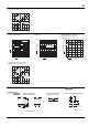
DIMENSIONS (Unit: mm inch)
1 Form A and 2 Form A types
ACCESSORIES
(Terminal sockets)
HE RELAY
ACCESSORIES
FEATURES
1. Snap-in mounting to DIN rails is
possible.
Can be inserted into 35 mm wide DIN
rails. Removal is easy, too.
2. Sure and easy wiring
The use of UP terminals makes wiring
exceptionally easy and sure.
3. Hold-down clips can be stored in
main unit
Because the hold-down clips can be
stored in the main unit, there is no need
to remove them when, for example,
wiring is changed.
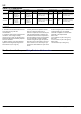
TYPES
SPECIFICATIONS
No. of poles Types Part No.
Packing quantity
Carton Case
For 1 Form A Single side stable type JH1-SF 10 pcs. 50 pcs.
For 2 Form A Single side stable type JH2-SF 10 pcs. 50 pcs.
Item Specifications
Arrangement 1 Form A 2 Form A
Max. continuous current 30A 250V AC 20A 250V AC
Breakdown voltage (initial) 2,000 Vrms for 1min (between terminals) (Detection current: 10mA.)
Insulation resistance Min. 100M (between poles)
Heat resistance 150C 3C for 1 hour
External dimensions
5
4
3
2
1
7
8
6
9
.354
9
.354
22
.866
60
2.362
10.25 8.4
.404 .331
7.2
.283
9.2
.362
14.4
.567
11
.433
11
.433
1
2
1
34
5
7
86
34
1.339
70
2.756
4
.157
.630
16
23
.906
Lot No.
M.157×4
M4×4 screw
M.138×4
M3.5×4 screw
Note: The JH1-SF (1 Form A single side stable type) does not have receptacles (tooth rests) for numbers 2, 3, 7, and 8.
The JH2-SF (2 Form A single side stable type) does not have receptacles (tooth rests) for numbers 7 and 8.
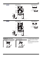
Panel cutout
Relay mounting diagram
40
1.575
2-4.2 dia. hole
(or 2-M4 screw hole)
2-.165 dia. hole
(or 2-M.157 screw hole)
61
2.402