
Datasheet

10
Amplifier
(Blue) 0 V
IO-Link master
(Black) Communication output (C/Q)
(White) Control output (DO)
(Brown) +V
0 V
C/Q
DI
+V
Color code
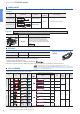
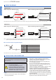
WIRING DIAGRAMS
FX-551L3-P-C2
Discrete wire type
FX-551L3-P-J
M12 connector type
Note: When the sensor is used as an ordinary sensor, the communication output (C/Q) provides the same output operation as the control output (DO).
Note: When the sensor is used as an ordinary sensor, the communication output (C/Q) provides the same output operation as the control output (DO).
Notes: 1) When the sensor is used as an ordinary sensor, the communication output (C/Q) provides the same output operation as the control output (DO).
2) When wiring with the discrete wire or extending the cable from the M12 connector, separately prepare commercially available M12 connector cable.
M12 connector terminal arrangement diagram
<When using as an ordinary sensor>
<When using as an ordinary sensor>
<When connecting to the IO-Link master>
<When connecting to the IO-Link master>
PRECAUTIONS FOR PROPER USE
• Never use this product as a sensing device
for personnel protection.
• In case of using sensing devices for
personnel protection, use products which
meet laws and standards, such as OSHA,
ANSI or IEC etc., for personnel protection
applicable in each region or country.
• This catalog is a guide to select a suitable product. Be
sure to read instruction manual attached to the product
prior to its use.
Wiring
• Make sure that the power supply is OFF while adding or
removing the ampliers.
• Note that if a voltage exceeding the rated range is
applied, or if an AC power supply is directly connected,
the product may get burnt or damaged.
• Note that short-circuit of the load or wrong wiring may
burn or damage the product.
• Do not run the wires together with high-voltage lines or
power lines, or put them in the same raceway. This can
cause malfunction due to induction.
• Verify that the supply voltage variation is within the rating.
• If power is supplied from a commercial switching
regulator, ensure that the frame ground (F.G.) terminal of
the power supply is connected to an actual ground.
• In case noise generating equipment (switching regulator,
inverter motor, etc.) is used in the vicinity of this product,
connect the frame ground (F.G.) terminal of the equipment
to an actual ground.
• Make sure that stress by forcible bending or pulling is not
applied to the sensor cable joint and ber cable.
Terminal No. Designation
+V
Control output (DO)
0 V
Communication output (C/Q) (Note)
Control output (DO)
+V
0 V
Communication output (C/Q)
(Note)
+
−
Load
Load
50 mA max.
(Blue) 0 V
(Black) Communication
output (C/Q)
(Note)
(White) Control output (DO)
(Brown) +V
Amplifier
50 mA max.
Color code
Digital Fiber Sensor FX-550L SERIES
FX-550L
SERIES
+
−
Load
Load
0 V
Communication
output (C/Q)
(Note 1)
Control output (DO)
+V
M12 connector terminal No.
M12 connector
Amplifier
M12 connector
(Note 2)
50 mA max.
50 mA max.
Amplifier
M12 connector
(Note 2)
0 V
IO-Link masterM12 connector
Communication output (C/Q)
Control output (DO)
+V
0 V
C/Q
DI
+V
M12 connector terminal No.