HR 200 - 300 HRS 300 - 500 Bedienungs- und Montageanleitung DE Operating and Installation Instructions GB Bitte um Weitergabe an den Benutzer! Please pass to the user! Notice d’utilisation et de montage A remettre à l’utilisateur! Id.Nr.
Sehr geehrter Kunde, Sie haben sich für die Warmwasserbereitung mit einem Speicher aus unserem Hause entschieden. Wir danken für Ihr Vertrauen. Sie erhalten ein formschönes Gerät, das nach dem letzten Stand der Technik gebaut wurde und den geltenden Vorschriften entspricht. Die durch kontinuierliche Forschung hochentwickelte Emaillierung sowie eine ständige Qualitätskontrolle während der Produktion, geben unseren Warmwasserspeichern technische Eigenschaften, die Sie immer schätzen werden.
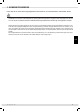
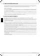
1. Sicherheitshinweise Lesen Sie alle in dieser Anleitung aufgeführten Informationen vor Inbetriebnahme aufmerksam durch! Installation und erste Inbetriebnahme sowie sämtliche weitere Eingriffe oder Reparaturen dürfen nur von einer konzessionierten Installationsfirma gemäß dieser Anleitung durchgeführt werden.
2.
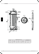
3. Skizzen 3.1 HR 200 G 1" G 1" d Vorlauf Magnesiumanode G 5/4" G 1/2" Warmwasser H Zierkulation G 3/4" Fühlerkanal Kaltwasser G 1" Rücklauf G 1" 180 DE D Stellfuß 3x 120° Draufsicht G 5/4" 30° Type HR 200 Id.Nr.
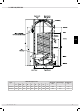
3.2 HR 300 DE Type HR 300 6 Abmessungen in mm ØD H Ød 600 1797 500 Heizfläche m2 2,60 Id.Nr.
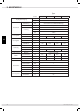
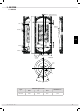
3.3 HRS 300, HRS 500 DE Type Abmessungen in mm I Einbaulänge Heizfläche m2 H ØD A B C E F HRS 300 1435 680 320 840 990 1160 345 1156 1050 1595 450 3,5 HRS 500 1806 750 350 1040 1290 1500 370 1498 1360 1970 530 6,0 Id.Nr.
4. Betriebsvoraussetzungen und wichtige Hinweise Das Gerät ist nur zur Warmwasserbereitung innerhalb geschlossener Räume geeignet und darf nur von zugelassenen Fachkräften (unter Berücksichtigung der facheinschlägigen Normen, z. B. ÖNORM B2531-1) installiert werden. Die Speicher sind ausschließlich gemäß den am Leistungsschild genannten Bedingungen einsetzbar. Neben den gesetzlich anerkannten nationalen Vorschriften und Normen (Österreich: ÖVE, ÖNORM usw.
Zwischen Sicherheitsventil und Kaltwasserzulauf des Speichers darf kein Absperrventil oder eine sonstige Drosselung eingebaut werden. Das Sicherheitsventil muss auf einen Ansprechdruck eingestellt sein, der unter dem Nenndruck des Speichers liegt. Vor endgültigem Anschluss des Speichers muss die Kaltwasserzuleitung durchgespült werden. Nach erfolgtem Wasseranschluss und blasenfreier Füllung des Speichers ist die Anschlussarmatur auf Funktion zu prüfen.
8. Zentralheizungsanschluss Vor Inbetriebnahme ist das Rohrregister bzw. der Doppelmantel zu spülen, um etwaige Verunreinigungen (z. B. Zunder) aus dem Heizkreis zu entfernen. Das Heizwasser muss entsprechend den nationalen Vorschriften und Normen (z. B. ÖNORM H5195-1) bei Inbetriebnahme aufbereitet werden und den Vorschriften entsprechen.
10. Korrosionsschutz Der emaillierte Kessel ist serienmäßig mit einer Magnesium-Stabanode geschützt. Die Magnesium-Stabanode verbraucht sich und muss deshalb alle 2 Jahre kontrolliert (siehe DIN 4753) und bei entsprechendem Verbrauch (2/3 des Materials) erneuert werden. Für eine ordnungsgemäße Funktion der Anoden ist eine Mindestleitfähigkeit des Wassers von 150 μs erforderlich. Beim Nachrüsten einer Fremdstromanode ist unbedingt darauf zu achten, dass alle im Speicher eingebauten Magnesium-Stabanoden (z.
Bei Frostgefahr ist weiters zu beachten, dass nicht nur das Wasser im Warmwasserbereiter und in den Warmwasserleitungen einfrieren kann, sondern auch in allen Kaltwasserzuleitungen zu den Gebrauchsarmaturen und zum Gerät selbst. Es ist daher zweckmäßig, alle wasserführenden Armaturen und Leitungen (auch Heizkreis = Register) zurück bis zum frostsicheren Teil der Hauswasseranlage (Hauswasseranschluss) zu entleeren.
15. Einbauheizung Die Elektro-Einbauheizungen der Typenreihe REU1STB sind als Hauptheizung für elektrisch beheizte Warmwasserbereiter wartungs- und pflegefrei. Nur bei stark kalkhaltigem Wasser ist es eventuell notwendig, in gewissen Zeitabständen die Heizkörper vom Kesselstein zu befreien. Die Elektro-Einbauheizungen werden nach den geltenden Vorschriften erzeugt und sind ÖVE- bzw. VDE- sicherheitsgeprüft.
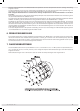
18. Skizzen und technische Daten 18.1 Aufbauskizze REU1STB 18.2 Schaltbild Der Elektrische Anschluss ist nach dem an der Innenseite der Schutzkappe aufgeklebten Anschlussschema durchzuführen. DE 14 kW kW mm senkrecht von unten nur in Liegespeicher - kW waagrecht x Einbaulänge über externen Schütz ~230 3 direkt 3,0 2 V Montagemöglichkeit 1 kW Schaltgruppe Heizkörperanzahl Nennspannung REU1STB 3,0 Nennleistung Type Schaltung 1 3,0 - - 450 x x - Flanschdurchmesser 18.
19. Schaltschemen DE Id.Nr.
20. Elektrischer Anschluss Die Montage des Heizeinsatzes und die erste Inbetriebnahme darf nur durch einen Fachmann erfolgen, der damit die Verantwortung für die ordnungsgemäße Ausführung und Ausrüstung übernimmt. Der elektrische Anschluss ist grundsätzlich nach dem beiliegenden typenbezogenen Schaltbild vorzunehmen! Auf die richtige Anschlussspannung achten! Alle berührbaren Metallteile des Behälters sind in die Schutzmaßnahme einzubeziehen.
Ersatzteile für HR und HRS Artikel Details Abdeckung für Thermometer HRS HR 200 Artikelnummer 500 48,5 x 48,5 X X 43869 Abdeckung Schlitz (ATR) 75,5 x 48,5 X X 43877 Anode Mg - Kette D 33 x 807 alternativ für MgAnode X X Außenhülle 200l silbergrau X 300 Bild 300 X X A05107 240879 DE Außenhülle 300l Außenhülle 300l X silbergrau silbergrau X Außenhülle 500l silbergrau Deckel D 680 x 50 Deckel D 760 x 50 schwarz Deckel D 610 x 50 schwarz Dichtung für Mg-Anode D 20 d
Artikel DE HRS Details HR Bild 300 500 200 300 X X Artikelnummer Fuß M10 x 68 X X Kleberosette D 75 d 48,5 x 3 schwarz X X 162750 Kleberosette D 100 d 65 x 3 schwarz X X 223933 Kunststoffmutter Warmwasser G1“ schwarz Magnesiumanode D 33 x 800 M8 x 10 Magnesiumanode D 33 x 1250 M8 x 10 Magnesiumanode D 33 x 480 M8 x 10 Magnesiumanode D 33 x 700 M8 x 10 Rosette D 81,5 x d 32,6 schwarz X X Rosette E-Heizung D 106 x d 61,5 X X Rosette Kaltwasser D 80 x d 34,5 x 25
Artikel HRS Details 300 HR 500 Bild 200 300 X X Artikelnummer Rosette Zirkulation D 77 x d 27,7 x 25 Rosette Zirkulation D 80 x d 34,5 x 25 Stützscheibe D 180 X X X X 210807 Verschlussschraube G 5/4“ M8 X X X X 114173 X X 59782 59808 DE Verschlussschraube G 5/4“ X X 233932 Verschlussschraube G 6/4“ X X 143586 Verschlussschraube G 1“ Zeigerthermometer D 63 X 3 Wege Ventil m. KVSR 22 mm F. CU- 22 mm X Id.Nr.
Garantie, Gewährleistung und Produkthaftung Die Gewährleistung erfolgt gemäß den gesetzlichen Bestimmungen der Republik Österreich sowie der EU. 1.
Dear customer, You have selected our water heater for heating your water. Thank you for the confidence you have shown in us. You have purchased an attractive unit which was constructed according to the state of the art and which meets all the appropriate regulations. Our continuously developed and improved enameling as well as constant quality inspection during production give our water heaters technical advantages that will serve you for years to come.
1. Safety instructions Please carefully read all information provided in this set of instructions prior to commissioning! The installation and initial commissioning, as well as all other interventions or repairs, may only be carried out by a licensed installation company in accordance with these instructions.
2. Size chart Type Unit Power supply Connection HR 200 Output Pressure vessel V 230 Inch 5/4 stainless steel (CW602N brass) Incoloy 825 kW 3 Btu/h 10243 kj/h 10800 Steel enamelled in accordance with DIN 4753 L Material Tube register 193 274 Outer sheath Dimensions Weight Connections Performance data Id.Nr.: 241525-0 DE - GB - F 269 448 Steel enamelled in accordance with DIN 4753 Diameter mm Heating surface m2 Ø 33.7 / 1.8 1.80 2.
3. Drawings 3.1 HR 200 Hot water Magnesium anode G 5/4“ Flow Sensor pipe Circulation Return flow GB Cold water foot Top view Type HR 200 24 Dimensions in mm ØD H ØD 600 1340 500 Heating surface m2 1,80 Id.Nr.
3.2 HR 300 Hot water Section B-B Magnesium anode Thermometer Flow Section A-A Circulation Sensor pipe GB Return flow Cold water foot Type HR 300 Id.Nr.
3.3 HRS 300, HRS 500 Magnesium anode Magnesium anode and PU insulation Hot water Flow 500 lt. as shown 300 and 400 lt.
4. Operating requirements and important notes This appliance is intended only for heating water within enclosed spaces and may be installed only by approved specialists (in accordance with the relevant norms, such as ÖNORM B2531-1). The appliance may be used only under the conditions specified on the specification label (such as: ÖNORM H 5 195-1). The tanks are intended for use only under the conditions specified on the specification label.
The safety valve must be set to a response pressure which is less than the rated pressure of the tank. Before finally connecting the tank, flush the cold water line. After making the water connection and air-bubble free filling of the tank, check the fitting for proper function. When lifting or turning (venting) the safety valve test button, the water must flow out freely and without backing up through the expansion water outlet funnel.
8. Central heating connection The pipe register resp. the double shell must be rinsed prior to commissioning in order to remove any possible contaminations (e.g. scale) from the heating circuit. The heating water must be treated in accordance with the national regulations and standards (e.g. ÖNORM H5195-1) during commissioning and comply with the regulations.
10. Corrosion protection The enamelled boiler is protected by a magnesium rod-type anode as standard. The magnesium rod-type anode is sacrificial and must therefore be inspected every 2 years (see DIN 4753) and replaced as necessary (2/3 of the material). For the anodes to function properly, the water requires a minimum conductivity of 150 µs. When retrofitting an external current anode, ensure that all magnesium rod-type anodes (e.g.
14. Inspection, maintenance, care a) During the heat-up phase the expansion water must drip noticeably from the safety valve drain. When fully heated (~ 80° C) the expansion water makes up approximately 3.5% of the rated capacity of the water heater. Regularly check for proper function of the safety valve. When lifting or turning the safety valve test knob to the “Test” position, the water must flow unhindered from the safety valve body into the funnel.
15. Fitted heater The electrical fitted heaters of the RDU1STB series are the main heater for electrically heated hot water heaters. Under normal circumstances, they do not require any maintenance or other service intervention. However, if the lime concentration of the water is very high, it may be necessary to remove the boiler scale at certain intervals. The range of electrical fitted heaters of Austria Email AG is manufactured in conformity with the applicable rules and regulations.
18. Drawings and technical data 18.1 Assembly draft REU1STB 18.2 Schematic The electrical connection is to be carried out according to the connection diagram affixed to the inside of the protective cap. GB Attention! Inner circuit may not be changed Id.Nr.
19. Circuit diagrams Sensor Electric Heating 3-way switching valve For heating circuit GB Terminals on the inside unit Connection cable open closed heating cooling open closed open closed Use bridge Accumulator temperature sensor 3-way switching valve Attention! Inner circuit may not be changed 34 Id.Nr.
20. Electrical connection The installation of the heating element and commissioning must be carried out by a skilled person who assumes the responsibility for the proper execution and configuration in his/her capacity as a professional. As a basic rule, the electrical connection should be made as indicated on the enclosed, type-specific wiring diagram! Make sure the supply voltage is correct! All accessible metal parts of the tank must be covered by the safety/protection measure.
Spare parts for HR and HRS GB Item Details Cover for thermometer HRS HR 48.5 x 48.5 X X 43869 Slot cover (ATR) 75.5 x 48.5 X X 43877 Anode Mg chain D 33 x 807 alternative for Mg anode X X Outer sheath 200I Silver-grey Outer sheath 300l Silver-grey Silver-grey X X X Silver-grey Cover D 680 x 50 Cover D 760 x 50 black Cover D 610 x 50 black Seal for Mg anode D 20 d 8.
Item HRS Details HR Image 300 500 200 300 X X Item number Foot M10 x 68 X X Adhesive rosette D 75 d 48.5 x 3 black X X 162750 Adhesive rosette D 100 d 65 x 3 black X X 223933 Plastic nut Warm water G1“ black Magnesium anode D 33 x 800 M8 x 10 Magnesium anode D 33 x 1250 M8 x 10 Magnesium anode D 33 x 480 M8 x 10 Magnesium anode D 33 x 700 M8 x 10 Rosette D 81.5 x 32.6 black X X Rosette Electrical heating D 106 x 61.5 X X Rosette Cold water D 80 x d 34.
Item HRS Details 300 GB HR 500 Image 200 300 X X Item number Rosette Circulation D 77 x d 27.7 x 25 Rosette Circulation D 80 x d 34.5 x 25 Supporting disc D 180 X X X X 210807 Locking screw G 5/4“ M8 X X X X 114173 Locking screw G 5/4“ X X 233932 Locking screw G 6/4“ X X 143586 Locking screw G 1“ Dial indicator thermometer D 63 X 3-way switching valve m. KVSR 22 mm F. CU- 22 mm X 38 X X 59782 59808 X X 114009 X X X 7047 X X X 240874 Id.Nr.
Warranty, Guarantee and Product Liability The warranty is granted in accordance with the statutory provisions of the Republic of Austria, as well as of the EU. 1.
Cher client, Vous avez choisi un chauffe-eau de notre société pour votre production d’eau chaude. Nous vous remercions de nous faire confiance. L’installation qui vous est fournie est un bel appareil qui a été construit conformément aux technologies les plus récentes et qui satisfait aux réglementations en vigueur.
1. Consignes de sécurité Lisez attentivement toutes les informations indiquées dans ce mode d’emploi avant toute mise en service ! L’installation, la première mise en service ainsi que l’ensemble des interventions ou réparations supplémentaires doivent être effectuées uniquement par une société d’installation licenciée d’après ce mode d’emploi.
2.
3. Croquis 3.1 HR 200 Eau chaude Anode magnésium G 5/4“ Marche avant Canal capteur Circulation Marche arrière Eau froide Pied de support F Vue de dessus Types HR 200 Id.Nr.
3.2 HR 300 Eau chaude Coupe B-B Anode magnésium Thermomètre Marche avant Coupe A-A Cirkulation Canal capteur Marche arrière F Eau froide Pied de support Types HR 300 44 Dimensions en mm ØD H Ød Surface de chaleur en m2 600 1797 500 2,60 Id.Nr.
3.3 HRS 300, HRS 500 Anode magnésium Anode magnésium u. Isolation PU Eau chaude Marche avant 500 l comme indiqué 300 u. 400 lt. avec rotation de 60mm Canal capteur Circulation Canal capteur Longueur de montage max.
4. Conditions d’utilisation et consignes importantes Cet appareil est exclusivement conçu pour produire de l’eau chaude dans des pièces fermées et ne doit être installé que par des professionnels agréés (en observant les normes professionnelles applicables, par exemple la norme ÖNORM B2531-1). Les chauffe-eau doivent être exclusivement utilisés conformément aux conditions indiquées sur la plaque signalétique. En plus des réglementations et normes nationales en vigueur (Autriche : ÖVE, ÖNORM, etc.
Il est interdit de monter un robinet d’arrêt ou tout autre dispositif d’étranglement entre la soupape de sécurité et l’arrivée d’eau froide du chauffe-eau. La soupape de sécurité doit être réglée de manière à réagir à une pression inférieure à la pression nominale du chauffe-eau. Avant de raccorder définitivement le chauffe-eau, il faut rincer la conduite d’alimentation en eau froide.
8. Raccordement au chauffage central Avant la mise en service, il faut rincer le registre tubulaire ou le cylindre double afin d’en éliminer toute impureté (de la calamine par ex.) du circuit de chauffage. L’eau chaude doit être préparée conformément à la législation et aux normes nationales (par ex. ÖNORM H5195-1 en Autriche) lors de la mise en service et être conforme à la réglementation.
10. Protection contre la corrosion Le ballon en émail est protégé en série par une anode magnésium. L’anode magnésium s’use et doit donc être contrôlée tous les 2 ans (cf. DIN 4753) et changée en fonction de l’usure (2/3 du matériau). Le fonctionnement correct des anodes requiert une conductibilité minimale de l’eau de150 µs.
même. Il est donc nécessaire de vider tous les tuyaux et robinets d’amenée d’eau (également ceux du circuit de chauffage = échangeur tubulaire) jusqu’à la partie de l’installation d’eau sanitaire (raccord d’eau sanitaire) qui ne risque pas de geler. Lorsque le chauffe-eau est remis en service, veillez impérativement à ce qu’il soit rempli d’eau et que l’eau sortant des robinets et soupapes soit exempte de bulles. 14.
15. Eléments de chauffe encastrés Comme chauffage principal de chauffe-eau électriques, les éléments chauffants électriques de la Série RDU1STB ne requièrent aucun entretien. Uniquement en présence d’une eau très calcaire, il peut s’avérer nécessaire de détartrer les corps de chauffe de temps en temps. Les courants d’eau entraînés par les variations de température ne doivent pas être entravés.
18. Croquis et données techniques 18.1 Croquis de montage REU1STB 18.2 Image des connexions Le raccordement électrique doit être effectué selon le schéma de raccordement collé à l’intérieur du capot de protection sur le côté.
19. Schémas de connexion Capteur Chauffage électrique Electrovanne 3 voies Vers le circuit de chauffage F Bornes à l‘intérieur de l‘appareil Câble de raccordement ouvert rermè chauffer refroidir fermè ouvert ouvert fermè mettre en place des ponts capteur de la température enregistrée èlectrovanne à trois voies Attention ! les connexions internes ne doivent pas être modifiées Id.Nr.
20. Raccord électrique Le montage de l’élément chauffant encastré ainsi que la première mise en service sont impérativement à confier à un professionnel, qui assume la responsabilité de l’exécution et de l’équipement dans les règles de l’art. Le branchement électrique doit systématiquement respecter le schéma des connexions joint relatif au type d’appareil.
Pièces de rechange pour HR et HRS Article Détails Couvercle de protection pour le thermomètre HRS HR 48.5 x 48.5 X X 43869 Couvercle de protection de fente (ATR) 75.5 x 48.
Article F HRS Détails HR Image 300 500 200 300 X X Numéro d'article Pied M10 x 68 X X Rosace d'adhérence D 75 d 48.5 x 3 noir X X 162750 Rosace d'adhérence D 100 d 65 x 3 noir X X 223933 Ecrou en plastique Eau chaude G1“ noir Anode magnésium D 33 x 800 M8 x 10 Anode magnésium D 33 x 1250 M8 x 10 Anode magnésium D 33 x 480 M8 x 10 Anode magnésium D 33 x 700 M8 x 10 Rosace D 81,5 x d 32,6 noir X X Rosace E-chauffage D 106 x d 61.
Article HRS Détails 300 HR 500 Image 200 300 X X Numéro d'article Rosace Circulation D 77 x d 27.7 x 25 Rosace Circulation D 80 x d 34,5 x 25 Ecran de protection D 180 X X X X 210807 Vis d'arrêt G 5/4“ M8 X X X X 114173 Vis d'arrêt G 5/4“ X X 233932 Vis d'arrêt G 6/4“ X X 143586 Vis d'arrêt G 1“ Thermomètre indicateur D 63 X Electrovanne 3 voies m. KVSR 22 mm F. CU- 22 mm X Id.Nr.
Garantie, responsabilité et responsabilité du fait du produit La garantie et la responsabilité sont conformes aux dispositions légales de la République d’Autriche ainsi que de l’UE. 1.
Zentrale und Werk: Head Office and Factory: Siège et usine: Austria Email AG Austriastraße 6 A-8720 Knittelfeld Tel.: (03512) 700-0 Fax: (03512) 700-239 Internet: www.austria-email.at E-Mail: office@austria-email.at Anschriften der Verkaufsniederlassungen: Sales Office Addresses: Adresse des succursales de distribution: Wien, Niederösterreich, Burgenland A-1230 Wien, Zetschegasse 17 Tel.: (01) 615 07 27 Fax: (01) 615 07 27-260 E-Mail: bhrastnik@austria-email.