Hybrid IP-PBX Installation Manual Model No. KX-TDA50 Thank you for purchasing a Panasonic Hybrid IP-PBX. Please read this manual carefully before using this product and save this manual for future use. KX-TDA50: PSMPR Software File Version 4.0000 or later SD Logo is a trademark.
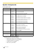
System Components System Components Table Category Model No.
Incompatible Panasonic Proprietary Telephones The Hybrid IP-PBX does not support the following telephones: • KX-T30800 series proprietary telephones and DSS consoles • KX-T61600 series proprietary telephones and DSS consoles • KX-T123200 series proprietary telephones and DSS consoles Notes • • For the equipment (e.g., Add-on Key Module, USB Module, Headset*1) that can be connected to a particular telephone, refer to the telephone's manual.
Important Safety Instructions SAFETY REQUIREMENTS When using your telephone equipment, basic safety precautions should always be followed to reduce the risk of fire, electric shock and injury to persons, including the following: 1. Read and understand all instructions. 2. Follow all warnings and instructions marked on the product. 3. Unplug this product from the wall outlet before cleaning. Do not use liquid cleaners or aerosol cleaners. Clean with a damp cloth. 4.
SAVE THESE INSTRUCTIONS Installation Manual 5
Precaution WARNING DO NOT REMOVE SD MEMORY CARD WHILE POWER IS SUPPLIED TO THE HYBRID.IP-PBX Doing so may cause the Hybrid IP-PBX to fail to start when you restart the system.
• • • Keep the unit away from heating appliances and devices that generate electrical noise such as fluorescent lamps, motors and televisions. These noise sources can interfere with the performance of the Hybrid IP-PBX. This unit should be kept free of dust, moisture, high temperature (more than 40 °C [104 °F]) and vibration, and should not be exposed to direct sunlight. If you are having problems making calls to outside destinations, follow this procedure to test the CO lines: 1.
Password Security Warning to the Administrator or Installer regarding the system password 1. Please provide all system passwords to the customer. 2. To avoid unauthorized access and possible abuse of the Hybrid IP-PBX, keep the passwords secret, and inform the customer of the importance of the passwords, and the possible dangers if they become known to others. 3. The Hybrid IP-PBX has default passwords preset. For security, change these passwords the first time that you program the Hybrid IP-PBX. 4.
When you ship the product Carefully pack and send it prepaid, adequately insured and preferably in the original carton. Attach a postage-paid letter, detailing the symptom, to the outside of the carton. DO NOT send the product to the Executive or Regional Sales offices. They are NOT equipped to make repairs. Product Service Panasonic Factory Service Centers for this product are listed in the service center directory. Consult your certified Panasonic dealer for detailed instructions.
Introduction This Installation Manual is designed to serve as an overall technical reference for the Panasonic Hybrid IPPBX, KX-TDA50. It provides instructions for installing the hardware, and programming the Hybrid IP-PBX using the KX-TDA50 Maintenance Console. The Structure of this Manual This manual contains the following sections: Section 1 System Outline Provides general information on the Hybrid IP-PBX, including the system capacity and specifications.
F.C.C. REQUIREMENTS AND RELEVANT INFORMATION 1. Notification to the Telephone Company This equipment complies with Part 68 of the FCC rules and the requirements adopted by the ACTA. On the side of this equipment is a label that contains, among other information, a product identifier in the following format: • US:AAAEQ##TXXXX If requested, this number must be provided to the telephone company. Installation must be performed by a qualified professional installer.
7. Combined Use with Alarm Equipment If your home has specially wired alarm equipment connected to the telephone line, ensure the installation of this equipment does not disable your alarm equipment. If you have questions about what will disable alarm equipment, consult your telephone company or a qualified installer. Note This equipment has been tested and found to comply with the limits for a Class B digital device, pursuant to Part 15 of the FCC Rules.
For Cell Station CAUTION Any changes or modifications not expressly approved by the party responsible for compliance could void user's authority to operate this device. Note This equipment has been tested and found to comply with the limits for a Class B digital device, pursuant to Part 15 of the FCC Rules. These limits are designed to provide reasonable protection against harmful interference in a residential installation.
Table of Contents 1 System Outline ..................................................................................... 17 1.1 1.1.1 1.2 1.2.1 1.2.2 1.3 1.3.1 1.4 1.4.1 1.4.2 1.4.3 2 Installation............................................................................................. 31 2.1 2.1.1 2.2 2.2.1 2.2.2 2.2.3 2.2.4 2.2.5 2.2.6 2.2.7 2.2.8 2.2.9 2.2.10 2.2.11 2.3 2.3.1 2.3.2 2.3.3 2.4 2.4.1 2.4.2 2.4.3 2.4.4 2.4.5 2.4.6 2.4.7 2.4.8 2.5 2.5.1 2.5.2 2.5.3 2.5.4 2.5.5 14 System Highlights..
2.5.6 2.5.7 2.6 2.6.1 2.6.2 2.6.3 2.6.4 2.7 2.7.1 2.7.2 2.7.3 2.7.4 2.7.5 2.7.6 2.7.7 2.7.8 2.8 2.8.1 2.9 2.9.1 2.10 2.10.1 2.11 2.11.1 3 Guide for the Hybrid IP-PBX PC Programming Software ............... 129 3.1 3.1.1 3.2 3.2.1 3.3 3.3.1 4 Overview ........................................................................................................................ 130 Overview .........................................................................................................................
Installation Manual
Section 1 System Outline This section provides general information on the Hybrid IPPBX, including the system capacity and specifications.
1.1 System Highlights 1.1 System Highlights 1.1.1 System Highlights Networking Features The Hybrid IP-PBX supports the following private networking features: TIE Line Service PBXs can be connected via a privately leased telephone lines forming a private network. These "TIE lines" provide a cost-effective way to route calls and communications, and are often used to connect corporate offices located in different cities.
1.1 System Highlights Third Party CTI Applications The Hybrid IP-PBX supports industry standard protocols, allowing third-party CTI applications to be integrated with the Hybrid-IP PBX and its extensions. Voice Mail Features A Voice Processing System (VPS) can be connected to the Hybrid IP-PBX to provide Voice Mail (VM) and Automated Attendant (AA) services. A Panasonic VPS which supports DPT (Digital) Integration can be connected to the Hybrid IP-PBX effortlessly and with minimal setup required.
1.2 Basic System Construction 1.2 Basic System Construction 1.2.1 Main Unit The main unit is equipped with 4 analog CO line ports (one LCOT4 card) and 4 extension ports (Super Hybrid Ports). For system expansion, optional service cards can be installed, and an additional AC adaptor can also be connected.
1.2 Basic System Construction 1.2.
1.
1.3 Optional Equipment 1.3 Optional Equipment 1.3.1 Optional Equipment Model No. Model Name Maximum Quantity Description KX-TDA5105 Memory Expansion Card (MEC) Memory expansion card to increase system data storage space, double the number of DPTs (using Digital XDP connection), and display language selection for VM Menu. To be installed in the MEC slot. 1 KX-TDA5161 4-Port Doorphone Card (DPH4) 4-port doorphone card for 4 doorphones, 4 door openers or external relays, and 4 external sensors.
1.3 Optional Equipment Model Name KX-TDA5193 4-Port Caller ID Card (CID4) 4-port Caller ID signal type FSK/FSK (with Call Waiting Caller ID [Visual Caller ID])/DTMF. To be mounted on the LCOT4 card. 3 KX-TDA5196 Remote Card (RMT) Analog modem card for remote communication with the Hybrid IP-PBX. ITU-T V.90 support. 1 KX-TDA5470 4-Channel VoIP Extension Card (IP-EXT4) 4-channel VoIP extension card. Compliant with Panasonic proprietary protocol, and ITU-T G.729a and G.711 CODEC methods.
1.4 Specifications 1.4 Specifications 1.4.1 General Description Switching AC Adaptor Non-blocking AC Input • • DC Output 40 V; 1.38 A (55.2 W) DC Input • • Panasonic PSLP1244: 100 V AC to 240 V AC; 1.5 A; 50 Hz/60 Hz Panasonic PSLP1434: 110 V AC to 240 V AC; 1.35 A; 50 Hz/60 Hz DC IN 1: 40 V; 1.38 A (55.2 W) DC IN 2: 40 V; 1.38 A (55.
1.4 Specifications Extension Connection Cable SLT 1-pair wire (T, R) DPT 1-pair wire (D1, D2) or 2-pair wire (T, R, D1, D2) APT 2-pair wire (T, R, D1, D2) PT-interface CS 1-pair wire (D1, D2) DSS Console and Add-on Key Module 1-pair wire (D1, D2) Dimension 275 mm (W) × 376 mm (H) × 117 mm (D) (10-4/5 in × 14-4/5 in × 4-3/5 in) Weight (when fully mounted) Under 3.5 kg (7.
1.4 Specifications 1.4.
1.4 Specifications 1.4.3 System Capacity Maximum CO Line and VoIP Line The Hybrid IP-PBX supports the following number of CO lines and VoIP lines. Line Type Maximum Number CO Line 12 VoIP Line 4 Maximum Terminal Equipment The following number of items of terminal equipment can be supported by the Hybrid IP-PBX. Depending on the type and total number of items of equipment to be connected, the MEC card may be required.
1.4 Specifications Note Devices connected to the Hybrid IP-PBX that exceed the system capacity will not function. MEC Card Calculation Calculate the MEC figure from the type and total number of items of equipment to be connected. If the MEC figure exceeds 28, you need to install an MEC card. Note that you also need to connect an additional AC adaptor in this case.
1.4 Specifications AC Adaptor Selection You must connect an additional AC adaptor in any of the following conditions: • A total of more than 4 APTs, DPTs (except KX-T7600 series), and DSS consoles (except KX-T7600 series) are connected. • More than 4 CSs are connected. • An MEC card is required to support a configuration with a total MEC figure exceeding 28. Note For how to connect an AC adaptor or additional AC adaptor, refer to "2.11.1 Starting the Hybrid IPPBX".
Section 2 Installation This section describes the procedures to install the Hybrid IPPBX. Detailed instructions for planning the installation site, installing the optional service cards, and cabling of peripheral equipment are provided. Further information on system expansion and peripheral equipment installation is included.
2.1 Before Installation 2.1 Before Installation 2.1.1 Before Installation Please read the following notes concerning installation and connection before installing the Hybrid IP-PBX and terminal equipment. Be sure to comply with all applicable laws, regulations, and guidelines. Safety Installation Instructions When installing telephone wiring, basic safety precautions should always be followed to reduce the risk of fire, electric shock and injury to persons, including the following: 1.
2.1 Before Installation 4. Use 2-pair telephone cables when connecting PTs. Use 1-pair telephone cables when connecting SLTs, data terminals, answering machines, computers, Voice Processing Systems, etc. 5. Unplug the system from its power source when wiring, and plug the system back in only after all wiring is completed. 6. Mis-wiring may cause the Hybrid IP-PBX to operate improperly. Refer to Section 2 "Installation" when wiring the system. 7.
2.2 Installation of the Hybrid IP-PBX 2.2 Installation of the Hybrid IP-PBX 2.2.
2.2 Installation of the Hybrid IP-PBX 2.2.2 Names and Locations E F G H I J A K B C D A. B. C. D. E. F. G. H. I. J. K. L.
2.2 Installation of the Hybrid IP-PBX 2.2.3 Opening/Closing the Covers Opening the Covers 1. Pull the slide button to the right and, holding it, slide the cable cover upwards. Then turn the cable cover slightly to remove it. 1 Slide Button Cable Cover 2. Remove the three screws. Screw 3. Holding the protrusions on both sides of the front cover, swing the cover open.
2.2 Installation of the Hybrid IP-PBX Removing/Attaching the Front Cover If you prefer, you can remove the front cover. Removing the Front Cover Holding the front cover open at about a 45° angle, remove the front cover by pushing it in the direction of the arrow as shown below. Attaching the Front Cover Fit the front cover to the main unit as shown below, and then close the front cover.
2.2 Installation of the Hybrid IP-PBX Closing the Covers 1. Close the front cover, then tighten the three screws. Screw 2. Attach the rear hooks on the cable cover to the main unit, then swing the cable cover closed so that the front hooks fit in place. Cable Cover 3. Slide the cable cover down until it locks.
2.2 Installation of the Hybrid IP-PBX 2.2.4 Installation of the SD Memory Card LED SD Memory Card Slot Cover SD Memory Card CAUTION • • • • Use only the SD Memory Card included with the Hybrid IP-PBX, or a Panasonic optional upgrade SD Memory Card. The SD Memory Card contains software for all the processes of the Hybrid IP-PBX and all the customer data. The SD Memory Card must be inserted before startup. Do not remove the SD Memory Card while power is supplied to the Hybrid IP-PBX.
2.2 Installation of the Hybrid IP-PBX 2.2.5 Frame Ground Connection IMPORTANT Connect the frame of the Hybrid IP-PBX to ground. 1. 2. 3. 4. Loosen the screw. Screw Insert a grounding wire (user-supplied)*. Tighten the screw. Connect the grounding wire to ground. Grounding wire To ground * For grounding wire, green-and-yellow insulation is required, and the cross-sectional area of the conductor must be more than 0.75 mm2 or 18 AWG. • • • Be sure to comply with applicable local regulations (e.g.
2.2 Installation of the Hybrid IP-PBX 2.2.6 Installing/Removing the Optional Service Cards Slot Position 11*1 10*1 04 09 03 07 06 2 02* 08 05 01*3 *1 *2 *3 Slots 10 and 11 accept only cards that do not have external ports. Therefore, these slots do not have removable cover plates. Slot 02 has an LCOT4 card pre-installed. Slot 01 contains the pre-installed Super Hybrid Ports. No optional service card can be installed. Slot Restrictions The following table shows the slot restrictions.
2.2 Installation of the Hybrid IP-PBX Card Type SVM2 *1 *2 *3 Slot Number Max 02 03 04 05 06 07 08 09 10 11 2 Including one LCOT4 card that is installed by default. Only one of the HLC, DLC4, SLC4 or PLC4 card can be installed. A maximum of two DLC8, SLC8 and PLC8 cards can be installed. CAUTION To protect the main board from static electricity, do not touch parts on the main board or on the optional service cards. To discharge static electricity, touch ground or wear a grounding strap.
2.2 Installation of the Hybrid IP-PBX 2. Position the card in the open slot, making sure that the tabs on the both sides of the card fit into place. Then, holding the card firmly in place, lower the rear end so that the hole of the card fits over the extension bolt. Optional Service Card 1 2 Extension Bolt CAUTION When installing the optional service cards, do not put pressure on any parts of the main board (e.g., tall capacitors). Doing so may result in damage to the Hybrid IP-PBX. 3.
2.2 Installation of the Hybrid IP-PBX 4. Stick an appropriate optional card label (included) to the left side of the corresponding card. Optional Card Label 5. Connect a cable to an appropriate port of the card. For details about pin assignments, refer to the appropriate section in "2.3 Information about the CO Line Cards" and "2.4 Information about the Extension Cards". Note Make sure to connect cables after installing the card in the Hybrid IP-PBX, not before.
2.2 Installation of the Hybrid IP-PBX 6. Repeat the procedure for other cards. A. When installing a card in Slot 07, make sure to detach the LED holder first. After installing the card, reattach the LED holder.
2.2 Installation of the Hybrid IP-PBX B. When installing a card in Slot 11, tighten the card using the screw included with the card, instead of the extension bolt.
2.2 Installation of the Hybrid IP-PBX Cable Handling 1. Attach the strap included with the card to one of the connected cables. Strap 2. Bind all the connected cables together using the strap. 3. Repeat the procedure for other cards.
2.2 Installation of the Hybrid IP-PBX 4. Attach the main strap (included with the Hybrid IP-PBX) to any of the 5 rails depending on your preference.
2.2 Installation of the Hybrid IP-PBX 5. Bind all the connected cables together using the main strap, and then close the cable cover. For how to close the cable cover, refer to "2.2.3 Opening/Closing the Covers". Cable Cover Main Strap Notes • • For safety reasons, do not stretch, bend, or pinch the cables. If you prefer, you can cut the other side of the cable cover and run the cables through that opening. For safety reasons, smooth the cut edges.
2.2 Installation of the Hybrid IP-PBX Removing the Optional Service Cards 1. Loosen the extension bolt. 2. Holding the protrusions of the card, pull the card in the direction of the arrows. CAUTION When removing the optional service cards, do not put pressure on any parts of the main board (e.g., tall capacitors). Doing so may result in damage to the Hybrid IP-PBX.
2.2 Installation of the Hybrid IP-PBX 2.2.
2.2 Installation of the Hybrid IP-PBX 2.2.8 Wall Mounting (KX-TDA50) Mounting on Wooden Wall 1. Place the reference for wall mounting (on the last page of this manual) on the wall to mark the three screw positions. 130 mm (5-1/8 in) 250 mm (9-13/16 in) 2. Install the screws and washers (included) in the wall. Washer Drive the screw to this position. Notes • • Make sure that the screw heads are at the same distance from the wall. Install the screws perpendicular to the wall. 3.
2.2 Installation of the Hybrid IP-PBX Mounting on Concrete or Mortar Wall CAUTION Drive mounting screws into the wall. Be careful to avoid touching any metal laths, wire laths or metal plates in the wall. 1. Place the reference for wall mounting (on the last page of this manual) on the wall to mark the three screw positions. 130 mm (5-1/8 in) 250 mm (9-13/16 in) 2. Install three anchor plugs (user-supplied) in the wall. Hammer Anchor Plug 8 mm (5/16 in) 30 mm (1-3/16 in) 3.
2.2 Installation of the Hybrid IP-PBX Notes • • • 54 Do not block the openings of the cabinet. Leave at least 20 cm (8 in) of space above and 10 cm (4 in) to the sides of the Hybrid IP-PBX for ventilation. Make sure that the surface behind the cabinet is flat and free of obstacles, so that the openings on the back of the cabinet will not be blocked. Be careful not to drop the cabinet.
2.2 Installation of the Hybrid IP-PBX 2.2.9 Attaching a Ferrite Core A ferrite core must be attached when an RJ45 connector is connected to the IP-EXT4 card. Attaching to an RJ45 Connector For the IP-EXT4 Card Wrap the cable once around the ferrite core, then close the case of the ferrite core. Attach the ferrite core 5 cm away from the connector. The ferrite core is included with the card.
2.2 Installation of the Hybrid IP-PBX 2.2.10 Wall Mounting (AC Adaptor) Mounting on Wooden Wall 1. Place the reference for wall mounting (on the following page) on the wall to mark the two screw positions. 110 mm (4-5/16 in) 2. Install the screws and washers (included) in the wall. Washer Drive the screw to this position. Notes • • Make sure that the screw heads are at the same distance from the wall. Install the screws perpendicular to the wall. 3. Hook the AC adaptor on the screw heads.
2.2 Installation of the Hybrid IP-PBX Mounting on Concrete or Mortar Wall CAUTION Drive mounting screws into the wall. Be careful to avoid touching any metal laths, wire laths or metal plates in the wall. 1. Place the reference for wall mounting (on the following page) on the wall to mark the two screw positions. 110 mm (4-5/16 in) 2. Install two anchor plugs (user-supplied) in the wall. Hammer Anchor Plug 8 mm (5/16 in) 30 mm (1-3/16 in) 3. Install the screws (included) in the wall.
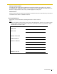
2.2 Installation of the Hybrid IP-PBX Reference for Wall Mounting Please copy this page and use as a reference for wall mounting. Install a screw here. 110 mm (4-5/16 in) Install a screw here. Note Make sure to set the print size to correspond with the size of this page. If the dimension of the paper output still deviates slightly from the measurement indicated here, use the measurement indicated here.
2.2 Installation of the Hybrid IP-PBX 2.2.11 Surge Protector Installation Overview A massive electrical surge can be caused if lightning strikes a telephone cable 10 m (33 ft) above ground, or if a telephone line comes into contact with a power line. A surge protector is a device that is connected to a CO line to prevent potentially dangerous electrical surges from entering the building via the CO line and damaging the Hybrid IP-PBX and connected equipment.
2.2 Installation of the Hybrid IP-PBX Outside Installation (Main Building) Surge Protector CO Line (Another Building) CO Line SLT Terminal Board Extn. SLT Hybrid IP-PBX Extn. Extn. Surge Protector PT CS Extn. PT CS Ground Extn.: Extension Line If you install an extension outside of the building, the following precautions are recommended: a. Install the extension wire underground. b. Use a conduit to protect the wire.
2.2 Installation of the Hybrid IP-PBX 1. Connect the ground rod to the surge protector using a grounding wire with a cross-sectional area of at least 1.3 mm2. 2. Bury the ground rod near the protector. The grounding wire should be as short as possible. 3. The grounding wire should run straight to the ground rod. Do not run the wire around other objects. 4. Bury the ground rod at least 50 cm (20 in) underground. Notes • • The above figures are recommendations only.
2.3 Information about the CO Line Cards 2.3 Information about the CO Line Cards 2.3.1 LCOT4 Card (KX-TDA5180) Function 4-port analog CO line card with 2 power failure transfer (PFT) ports. One CID4 card can be mounted on the LCOT4 card (refer to "2.3.2 CID4 Card (KX-TDA5193)").
2.3 Information about the CO Line Cards 2.3.2 CID4 Card (KX-TDA5193) Function 4-port Caller ID signal type FSK/FSK (with Call Waiting Caller ID [Visual Caller ID])/DTMF. To be mounted on the LCOT4 card.
2.3 Information about the CO Line Cards 2.3.3 IP-GW4 Card (KX-TDA5480) Function 4-channel VoIP gateway card. This card also enables CTI communication and system programming via a LAN. Compliant with VoIP H.323 V.2 protocol, and ITU-T G.729a, G.723.1, and G.711 CODEC methods. CSTA Phase 3 protocol compatible.
2.3 Information about the CO Line Cards Pin Assignments RJ45 Connector (10BASE-T/100BASE-TX) TPO+ TPOTPI+ TPI- 1 8 Signal Name Input (I)/Output (O) Function TPO+ O Transmit data+ TPO- O Transmit data- TPI+ I Receive data+ TPI- I Receive data- – – Reserved LED Indications Indication Color Description ON LINE Green On-line status indication • ON: On-line mode • OFF: Off-line mode • Flashing: Maintenance mode Note If the LINK indicator is OFF, the ON LINE indicator will also be OFF.
2.4 Information about the Extension Cards 2.4 Information about the Extension Cards 2.4.1 HLC4 Card (KX-TDA5170) Function 4-port extension card for SLTs, APTs, DSS consoles, a Voice Processing System (VPS), and PT-interface CSs.*1 RJ11 To extension Accessories and User-supplied Items Accessories (included): Extension Bolt × 1, Strap × 1 User-supplied (not included): RJ11 connector Note For details about connecting the CS, refer to "2.7.7 Connecting a Cell Station to the Hybrid IP-PBX".
2.4 Information about the Extension Cards 2.4.2 DLC4 Card (KX-TDA5171) Function 4-port digital extension card for DPTs, DSS consoles, a VPS, and PT-interface CSs.*1 RJ11 To extension Accessories and User-supplied Items Accessories (included): Extension Bolt × 1, Strap × 1 User-supplied (not included): RJ11 connector Note For details about connecting the CS, refer to "2.7.7 Connecting a Cell Station to the Hybrid IP-PBX".
2.4 Information about the Extension Cards 2.4.3 SLC4 Card (KX-TDA5173) Function 4-port extension card for SLTs.
2.4 Information about the Extension Cards 2.4.4 PLC4 Card (KX-TDA5175) Function 4-port extension card for APTs, DSS consoles, and a VPS.
2.4 Information about the Extension Cards 2.4.5 DLC8 Card (KX-TDA5172) Function 8-port digital extension card for DPTs, DSS consoles, a VPS, and PT-interface CSs.*1 RJ11 To extensions Accessories and User-supplied Items Accessories (included): Extension Bolt × 1, Strap × 1 User-supplied (not included): RJ11 connector Note For details about connecting the CS, refer to "2.7.7 Connecting a Cell Station to the Hybrid IP-PBX".
2.4 Information about the Extension Cards 2.4.6 SLC8 Card (KX-TDA5174) Function 8-port extension card for SLTs.
2.4 Information about the Extension Cards 2.4.7 PLC8 Card (KX-TDA5176) Function 8-port extension card for APTs, DSS consoles, and a VPS.
2.4 Information about the Extension Cards 2.4.8 IP-EXT4 Card (KX-TDA5470) Function 4-channel VoIP extension card. Compliant with Panasonic proprietary protocol, and ITU-T G.729a and G.711 CODEC methods. RJ45 LEDs To LAN Accessories and User-supplied Items Accessories (included): Ferrite core × 1, Extension Bolt × 1, Strap × 1 User-supplied (not included): RJ45 connector Notes • • The maximum length of the cable to be connected to this optional service card is 100 m (328 ft).
2.4 Information about the Extension Cards LED Indications Indication Color Description ON LINE Green On-line status indication • ON: At least one port is in use (an IP-PT is connected) • OFF: No ports are in use (no IP-PTs are connected) Note If the LINK indicator is OFF, the ON LINE indicator will also be OFF.
2.5 Information about the Other Cards 2.5 Information about the Other Cards 2.5.1 DPH4 Card (KX-TDA5161) Function 4-port doorphone card for 4 doorphones, 4 door openers or external relays, and 4 external sensors.
2.
2.5 Information about the Other Cards Connection Diagram for External Sensors and External Relays Power to the external sensor is provided from the DPH4 card and must be grounded through the DPH4 card as indicated in the diagram below. A pair of "sensor" and "common" lines must be connected to the DPH4 card for each external sensor. The Hybrid IP-PBX detects input from the sensor when the signal is under 100 Ω.
2.5 Information about the Other Cards 2.5.2 ECHO8 Card (KX-TDA5166) Function 8-channel card for echo cancellation during conferences. Accessories and User-supplied Items Accessories (included): Extension Bolt × 1, Screw × 1 User-supplied (not included): none Note To establish a conference call involving 6 to 8 parties, install an ECHO8 card and enable echo cancellation for conferences using the KX-TDA50 Maintenance Console. For details, refer to "Echo Cancel—Conference" in "2.8.
2.5 Information about the Other Cards 2.5.3 MSG2 Card (KX-TDA5191) Function 2-channel message card.
2.5 Information about the Other Cards 2.5.4 SVM2 Card (KX-TDA5192) Function 2-channel simplified voice message card for Simplified Voice Message feature.
2.5 Information about the Other Cards 2.5.5 EXT-CID Card (KX-TDA5168) Function Sends Caller ID signals to extension ports.
2.5 Information about the Other Cards 2.5.6 MEC Card (KX-TDA5105) Function Memory expansion card to increase system data storage space, double the number of DPTs (using Digital XDP connection), and display language selection for VM Menu. To be installed in the MEC slot. MEC Card MEC Slot Accessories and User-supplied Items Accessories (included): none User-supplied (not included): none CAUTION Make sure to insert the MEC card between the guide rails until it locks into the MEC slot.
2.5 Information about the Other Cards Removing the MEC Card Pull open the guide rails using a flathead screwdriver and, while holding them open, remove the MEC card.
2.5 Information about the Other Cards 2.5.7 RMT Card (KX-TDA5196) Function Analog modem card for remote communication with the Hybrid IP-PBX. ITU-T V.90 support. RMT Card RMT Slot Accessories and User-supplied Items Accessories (included): none User-supplied (not included): none CAUTION Make sure to insert the RMT card between the guide rails until it locks into the RMT slot. Push the card firmly into place until you hear a clicking sound.
2.5 Information about the Other Cards Removing the RMT Card Pull open the guide rails using a flathead screwdriver and, while holding them open, remove the RMT card.
2.6 Connection of Extensions 2.6 Connection of Extensions 2.6.
2.6 Connection of Extensions DSS Console PT-interface CS DPT APT SLT KX-T7600 series Other Super Hybrid Ports (Main Board) SLC4, SLC8 Cards DLC4, DLC8 Cards PLC4, PLC8 Cards HLC4 Card " " indicates that the extension card or Super Hybrid Ports support the terminal.
2.6 Connection of Extensions 2.6.2 Parallel Connection of the Extensions Any SLT can be connected in parallel with an APT or a DPT as follows. Note In addition to an SLT, an answering machine, a fax machine or a modem (PC) can be connected in parallel with an APT and a DPT. With APT For parallel connection, eXtra Device Port (XDP) mode must be disabled for that port through system programming. Refer to "1.13.2 Paralleled Telephone" and "1.5.
2.6 Connection of Extensions Using a Modular T-Adaptor To a Super Hybrid Port Modular T-Adaptor 2-conductor wiring cord Connect pins "T" and "R". 4-conductor wiring cord Connect pins "D1" and "D2". DPT SLT Using an EXtra Device Port With KX-T7600 Series DPT To a Super Hybrid Port 2-conductor wiring cord Connect pins "T" and "R". 4-conductor wiring cord Connect pins "T", "R", "D1" and "D2".
2.6 Connection of Extensions With Other DPT To a Super Hybrid Port 2-conductor wiring cord Connect pins "T" and "R". 4-conductor wiring cord Connect pins "T", "R", "D1" and "D2".
2.6 Connection of Extensions 2.6.3 Digital EXtra Device Port (Digital XDP) Connection A DPT can be connected to another DPT on the Digital XDP connection. In addition, if the DPT is connected to a Super Hybrid Port, it can also have an SLT connected in Parallel mode or XDP mode. Notes • • • Both DPTs must be KX-T7600 series DPTs (except KX-T7640). Note that the KX-T7667 can only be connected as a slave DPT. Parallel mode or XDP mode can be selected through system programming.
2.6 Connection of Extensions Using an EXtra Device Port To DLC4/DLC8 card To a Super Hybrid Port (for connection of SLT) 4-conductor wiring cord Connect pins "T", "R", "D1" and "D2". 4-conductor wiring cord Connect pins "T", "R", 2-conductor wiring cord "D1" and "D2". Connect pins "T" and "R".
2.6 Connection of Extensions 2.6.4 First Party Call Control CTI Connection CTI connection between a PC and a KX-T7633/T7636 DPT provides first party call control. The CTI connection is made via a USB interface (version 2.0), and uses the TAPI 2.1 protocol. A USB Module (KX-T7601) must be connected to the KX-T7633/T7636 DPT. Note The operating system of the PC required for first party call control depends on your CTI application software. For details, refer to the manual for your CTI application software.
2.7 Connection of 2.4 GHz Portable Stations 2.7 Connection of 2.4 GHz Portable Stations 2.7.1 Overview The following equipment is required to connect the wireless system: CS: Cell Station (KX-T0141) This unit determines the area covered by the wireless system. Up to 2 calls can be made at the same time through each CS. PS: 2.4 GHz Portable Station (KX-TD7680/KX-TD7690) The KX-TDA50 can support up to 28 PSs. For more details about the PS, refer to the PS Operating Instructions.
2.7 Connection of 2.4 GHz Portable Stations 2.7.2 Procedure Overview When connecting the wireless system, use extreme care in conducting the site survey. An incorrectly performed site survey can result in poor service area, frequent noise, and disconnection of calls. 1. Investigate the installation site Refer to "2.7.3 Site Planning". a. Obtain a map of the CS installation site. b. Identify the service area required by the user on the map. c.
2.7 Connection of 2.4 GHz Portable Stations 4. Finish the site survey Refer to "2.7.6 After Site Survey". a. Return all DIP switches of each CS to the OFF position, and stop supplying power. b. Turn off the PS. 5. Connect the CS and PS to the Hybrid IP-PBX and test the operation Refer to "2.7.7 Connecting a Cell Station to the Hybrid IP-PBX". a. Connect the CSs to the Hybrid IP-PBX. b. Register the PSs to the Hybrid IP-PBX. c.
2.7 Connection of 2.4 GHz Portable Stations 2.7.3 Site Planning Choosing the best site for the CS requires careful planning and testing of essential areas. The best location may not always be convenient for installation. Read the following information before installing the unit. Understanding the Radio Waves Characteristics of Radio Waves The transmission of radio waves and the CS coverage area depend on the structure and materials of the building.
2.7 Connection of 2.4 GHz Portable Stations Object Material Transmission Tendency Wall Concrete The thicker they are, the less radio waves penetrate them. Ferroconcrete Radio waves can penetrate them, but the more iron there is, the more radio waves are reflected. Glass Radio waves usually penetrate them. Glass with wire net Radio waves can penetrate them, but tend to be reflected. Glass covered with heat-resistant film Radio waves are weakened considerably when they penetrate windows.
2.7 Connection of 2.4 GHz Portable Stations CS Coverage Area The example below shows the size of the coverage area of 1 CS if it is installed in an area with no obstacles. Note Radio signal strength levels are measured during the site survey (refer to "2.7.5 Site Survey"). A A Coverage Area Radio signal strength level is greater than "3". (About 50 m to 60 m [164 ft to 197 ft]) B B Gray Zone: Conversation will be intermittent C Good Coverage Area Radio signal strength level is greater than "8".
2.7 Connection of 2.4 GHz Portable Stations one CS becomes weak. However, if a PS moves away from a CS and there are no CSs available for handover, the PS may go out of range and the call could be lost. If the signal from the CS fades, due to the structure of the building, there may be some handover delay. The user will hear a range warning before handover in this case. This also applies in the case of interference from 2.4 GHz apparatus.
2.7 Connection of 2.4 GHz Portable Stations 2.7.4 Before Site Survey Setting and Installing the CS Temporarily for Site Survey 1. Switch the Radio Signal Test switch from OFF to ON. 2. Set the CS number switches as desired. DIP Switch OFF ON 1 2 CS Number Switch 3 4 Keep this switch at the default "OFF" position. Otherwise, the CS will not function. 5 6 CS no. 1 CS no. 2 CS no. 3 CS no. 4 Radio Signal Test Switch CS no. 5 CS no. 6 CS no. 7 CS no. 8 CS no.
2.7 Connection of 2.4 GHz Portable Stations 3. After setting the DIP switch, connect an AC adaptor or battery box to the CS using a power supply adaptor. Note The AC adaptor should be connected to a vertically oriented or floor-mounted AC outlet. Do not connect the AC adaptor to a ceiling-mounted AC outlet, as the weight of the adaptor may cause it to become disconnected. Telephone Cord Modular Power Supply Adaptor (PSZZ1TDA0142) To AC Adaptor (KX-A11/KX-TCA1)/ Battery Box (PSZZTD142CE) 4.
2.7 Connection of 2.4 GHz Portable Stations 2.7.5 Site Survey The PS has a Radio Signal Test mode that monitors the state of the radio link to the CS. After installing the CSs temporarily, set the PS to Radio Signal Test mode and measure each CS coverage area. Then, record the results on the map of the installation site. Testing the Radio Signal Strength Note Display prompts for the site survey are only available in English. 1. Enter Radio Signal Test mode.
2.7 Connection of 2.4 GHz Portable Stations 2. Measure the radio signal strength by moving towards and away from the CS. a. Move to the CS until the radio signal strength level becomes "12". b. Move away from the CS and identify the CS coverage area within which the radio signal strength level is greater than "8". Draw the area on the map. c. Move away from the CS and identify the CS coverage area within which the radio signal strength level is greater than "3". Draw the area on the map. PS CS NO.
2.7 Connection of 2.4 GHz Portable Stations b. Overlap the CS coverage areas of at least 2 CSs at any location in the installation site. CS no. 1 CS no. 2 CS no. 3 CS no. 4 c. Make sure that the radio signal strength level is greater than "3" at any location in the service area required by the user. Referring to the Stored Scan Data Using the KX-TD7680 1 9 1 Scan Data No. 0 to 9 Press 1, 9, and POWER for more than 2 seconds. Display example: When there is scan data NO.1 CS No.
2.7 Connection of 2.4 GHz Portable Stations Deleting the Stored Scan Data Using the KX-TD7680 1 9 2 Scan Data No. 0 to 9, or # for all data Press 1, 9, and POWER for more than 2 seconds. To the Desired Scan Data No. Using the KX-TD7690 1 9 Press 1, 9, and POWER for more than 2 seconds. 2 Scan Data No. 0 to 9, or # for all data To the Desired Scan Data No.
2.7 Connection of 2.4 GHz Portable Stations 2.7.6 After Site Survey After obtaining the proper measurement results, exit Radio Signal Test mode before connecting the CS to the Hybrid IP-PBX. 1. Keep pressing the POWER button on the PS until the PS is turned OFF. 2. Disconnect the AC adaptor or battery box from the CS and stop supplying electricity. 3. Switch all DIP switches on the CS from ON to OFF.
2.7 Connection of 2.4 GHz Portable Stations 2.7.7 Connecting a Cell Station to the Hybrid IP-PBX Refer to the following example to connect a CS to the Hybrid IP-PBX. Super Hybrid Port Cable 26 AWG: 24 AWG: 22 AWG: CAT 5: Maximum Distance 222 m (728 ft) 347 m (1138 ft) 500 m (1640 ft) 347 m (1138 ft) A Super Hybrid Port, or HLC4/DLC4/DLC8 card (RJ11) Signal Name D1 D2 Pin No. 1 2 3 4 CS (RJ11) Pin No.
2.7 Connection of 2.4 GHz Portable Stations Connecting the CS 1. Connect the cable from a Super Hybrid Port or the HLC4/DLC4/DLC8 card to the CS. Modular To a Super Hybrid Port, or HLC4/DLC4/DLC8 card 2. Pass the cable through the groove of the CS (in any direction depending on your preference).
2.7 Connection of 2.4 GHz Portable Stations Registering the PS The PS must be registered to the Hybrid IP-PBX before it can be used. Programming of both the PS and Hybrid IP-PBX is required. A PT with multiline display (e.g., KX-T7636 6-line display) is required to perform the Hybrid IP-PBX system programming. Note For details about system programming using a PT, refer to "1.13.28 PT Programming" in the Feature Manual and "2.1 PT Programming" in the PT Programming Manual.
2.7 Connection of 2.4 GHz Portable Stations PS Registration [690] ENTER PS No. Extn. No. 001 to 028 1 to 4 digits ENTER To the PS operation below END When the PS has not been registered yet When registering the PS for the first time, it is possible to select the desired language for the display. (You do not need to enter the PS system programming mode when registering for the first time.) Using the KX-TD7680 [ F2 ] [ F3 ] Press S2 repeatedly to select the desired language.
2.7 Connection of 2.4 GHz Portable Stations Using the KX-TD7690 Select "SYSTEM LOCK". SEL SEL CHNG S1 S1 Choose "Enable/Disable". System Lock Password ENTR System Lock Password 4 digits S1 4 digits ENABLE S1 DISABLE ENTR C.Tone S1 Setting the Personal Identification Number (PIN) for PS Registration To prevent registering the PS to a wrong Hybrid IP-PBX, a PIN for PS registration can be set to the Hybrid IP-PBX.
2.7 Connection of 2.4 GHz Portable Stations PS Termination Confirm the following before canceling the PS registration: • The PS is turned on. • The PS is within range. [691] PS No. 001 to 028 ENTER ENTER If "Rejected" or "Time out" is displayed CLEAR Press "CLEAR". YES To the PS operation below END Press "YES". If the registration information is still stored in the PS Using the KX-TD7680 Select "YES". Select the desired item. Select "DELETE SYSTEM". C.
2.7 Connection of 2.4 GHz Portable Stations 2.7.8 Wall Mounting 1. Place the reference for wall mounting (on the following page) on the wall to mark the 2 screw positions. 2. Install the 2 screws and washers (included) into the wall. Notes • • Make sure that the screw heads are at the same distance from the wall. Install the screws perpendicular to the wall. 3. Hook the CS on the screw heads.
2.7 Connection of 2.4 GHz Portable Stations Reference for Wall Mounting Please copy this page and use as a reference for wall mounting. Install a screw here. 71 mm (2-13/16 in) Install a screw here. Note Make sure to set the print size to correspond with the size of this page. If the dimension of the paper output still deviates slightly from the measurement indicated here, use the measurement indicated here.
2.8 Connection of Doorphones, Door Openers, External Sensors, and External Relays 2.8 Connection of Doorphones, Door Openers, External Sensors, and External Relays 2.8.1 Connection of Doorphones, Door Openers, External Sensors, and External Relays A maximum of 4 doorphones (KX-T30865), 4 door openers or external relays, and 4 external sensors can be connected to the Hybrid IP-PBX. Note Doorphones, door openers, external sensors, and external relays are user-supplied.
2.8 Connection of Doorphones, Door Openers, External Sensors, and External Relays 2. Pass the wires through the hole in the base cover, and attach the base cover to a wall using 2 screws. Screw To terminal box Note Two kinds of screws are included with KX-T30865. Please choose the appropriate kind for your wall type. : when a doorphone plate has been fixed to the wall : when you wish to install the doorphone directly to the wall 3. Connect the wires to the screws located in the front cover.
2.8 Connection of Doorphones, Door Openers, External Sensors, and External Relays Connection of Doorphones 1. Connect DPH4 Card to the terminal boxes using telephone line cords. Refer to "2.5.1 DPH4 Card (KX-TDA5161)" for pin assignments. 2. Connect the wires of doorphones 1 and 3 to the red and green screws on the terminal box. 3. Connect the wires of doorphones 2 and 4 to the yellow and black screws on the terminal box.
2.8 Connection of Doorphones, Door Openers, External Sensors, and External Relays Connection of Door Openers, External Sensors, and External Relays Use 8-pin and 10-pin terminal blocks (included with the card) for connection. 1. While pressing down on the hole at the top of the terminal block using a screwdriver, insert the wire into the side hole as shown below. Repeat this procedure for other door openers, external sensors, and external relays. Refer to "2.5.
2.9 Connection of Peripherals 2.9 Connection of Peripherals 2.9.1 Connection of Peripherals Cable 26 AWG to 22 AWG: CAT 5: Maximum Distance 10 m (32 ft) 10 m (32 ft) Cable 26 AWG to 22 AWG: CAT 5: Maximum Distance 10 m (32 ft) 10 m (32 ft) BGM/ Music on Hold Pager: Amplifier/Speaker Maximum Distance 2 m (6 ft) PC Printer PC CTI Server Maximum Distance 5 m (16 ft) BGM/MOH The Hybrid IP-PBX provides Background Music and Music on Hold. Only 1 external music source (e.g.
2.9 Connection of Peripherals Pager Only one paging device (user-supplied) can be connected to the Hybrid IP-PBX. CAUTION An External Paging Jack is a SELV port and should only be connected to an approved SELV device. PC/Printer (via RS-232C) The Hybrid IP-PBX is equipped with an RS-232C interface. This interface provides communication between the Hybrid IP-PBX and the user-supplied devices such as PC or line printers.
2.9 Connection of Peripherals For connecting a printer/PC with a 25-pin RS-232C connector Hybrid IP-PBX (9-pin) Printer/PC (25-pin) Circuit Type (EIA) Signal Name Pin No. Pin No.
2.9 Connection of Peripherals PC/CTI Server (via USB version 2.0) The Hybrid IP-PBX is equipped with a USB interface. This interface provides communication between the Hybrid IP-PBX and a PC or a CTI server. The PC is used for system programming, diagnostics and external system database storage (save/load) functions. The CTI server is used for connecting PCs on a LAN to provide third party call control CTI. The CTI connection uses the CSTA Phase 3 or TAPI 2.1 protocol.
2.10 Power Failure Connections 2.10 Power Failure Connections 2.10.1 Power Failure Connections When the power supply to the Hybrid IP-PBX fails, power failure transfer (PFT) will switch from the current connection to the Power Failure Connection. Refer to "1.13.9 Power Failure Transfer" in the Feature Manual for further information.
2.11 Starting the Hybrid IP-PBX 2.11 Starting the Hybrid IP-PBX 2.11.1 Starting the Hybrid IP-PBX CAUTION • • • • • The SD Memory Card must be inserted in the SD Memory Card slot of the main board before startup. Before touching the System Initialize Switch, discharge static electricity by touching ground or wearing a grounding strap. Once you have started the Hybrid IP-PBX and if you unplug the Hybrid IP-PBX, do not perform the following procedures to start the Hybrid IP-PBX again.
2.11 Starting the Hybrid IP-PBX 2. Plug the DC connector of the AC adaptor into DC IN 1. DC IN 1 DC Connector 1 2 AC Adaptor Notes • • The AC adaptor supplied with the Hybrid IP-PBX must be connected to DC IN 1. If an AC adaptor is connected only to DC IN 2, the Hybrid IP-PBX will not start. If you need to connect an additional AC adaptor, plug the DC connector of the additional AC adaptor into DC IN 2.
2.11 Starting the Hybrid IP-PBX 3. Plug the AC cord into the AC adaptor, and then plug the other end into an AC outlet. AC Adaptor AC Cord To AC outlet 4. Turn on the power switch. The RUN indicator will flash. Power Switch Notes • • For safety reasons, follow the procedures as indicated when turning on the Hybrid IP-PBX. For safety reasons, do not stretch, bend, or pinch the AC cord and the DC cable of the AC adaptor. 5.
2.
Section 3 Guide for the Hybrid IP-PBX PC Programming Software This section explains the installation and structure of the Hybrid IP-PBX PC Programming Software.
3.1 Overview 3.1 Overview 3.1.1 Overview KX-TDA50 Maintenance Console is designed to serve as an overall system programming reference for the Hybrid IP-PBX. To program and administer the Hybrid IP-PBX by PC, you need to install the KX-TDA50 Maintenance Console onto the PC. This manual describes overview and installation of the KX-TDA50 Maintenance Console only. KX-TDA50 Maintenance Console*1 Menu Bar System Menu *1 The contents and design of the software are subject to change without notice.
3.2 Connection 3.2 Connection 3.2.1 Connection Serial Interface Connection RS-232C Port To COM Port PC To USB Port PC USB Port Note For pin assignments and maximum cabling distance, refer to "2.9.1 Connection of Peripherals". LAN Connection via IP-GW4 Card RJ45 Switching Hub To network port PC Note For pin assignments and maximum cabling distance, refer to "2.3.3 IP-GW4 Card (KX-TDA5480)".
3.2 Connection External Modem Connection RS-232C Port (9-pin) To RS-232C port (25-pin) Modem To CO line/Hybrid IP-PBX extension port assigned as the CO line destination Hybrid IP-PBX (9-pin) External Modem (25-pin) Signal Name Pin No. Pin No.
3.3 Installation of the Hybrid IP-PBX PC Programming Software 3.3 Installation of the Hybrid IP-PBX PC Programming Software 3.3.
3.3 Installation of the Hybrid IP-PBX PC Programming Software Starting the KX-TDA50 Maintenance Console and Assigning the Basic Items (Quick Setup) When you start the KX-TDA50 Maintenance Console with the Installer Level Programmer Code and connect to the Hybrid IP-PBX for the first time after initialization (with the factory default setting), Quick Setup will launch automatically. During Quick Setup, you will set up the basic items. For details about the basic items, refer to "1.14.
3.3 Installation of the Hybrid IP-PBX PC Programming Software The system menu appears. You may now begin programming the Hybrid IP-PBX. Notes • • • During a long programming session, it is highly recommended that you periodically save the system data to the SD Memory Card. If the Hybrid IP-PBX undergoes a sudden power failure or if the system is reset for some reason, all the system data in RAM will be lost. However, if system data has been saved to the SD Memory Card, it can be easily restored.
3.3 Installation of the Hybrid IP-PBX PC Programming Software CAUTION Do not remove the SD Memory Card while power is supplied to the Hybrid IP-PBX. Doing so may cause the Hybrid IP-PBX to fail to start when you try to restart the system.
Section 4 Troubleshooting This section provides information on the Hybrid IP-PBX and telephone troubleshooting.
4.1 Troubleshooting 4.1 Troubleshooting 4.1.1 Installation PROBLEM Extension does not operate. PROBABLE CAUSE SOLUTION Bad extension card. • Exchange the card for a known working one. Bad connection between the Hybrid IP-PBX and telephone. • Take the telephone and plug it into the same extension port using a short telephone cord. If the telephone works, then the connection between the Hybrid IP-PBX and the telephone must be repaired. A telephone with an A-A1 relay is connected.
4.1 Troubleshooting PROBLEM PROBABLE CAUSE The ALARM indicator on the A major system error occurs in front of the cabinet turns on red. the Hybrid IP-PBX. SOLUTION • See the error log using the KX-TDA50 Maintenance Console (refer to "4.1.5 Troubleshooting by Error Log").
4.1 Troubleshooting 4.1.2 Connection Connection between the Hybrid IP-PBX and a PT: Can you dial an extension? CAUSE No SOLUTION The T/R is connected to the D1/D2. D1 T R D2 D1 T R D2 Hybrid IP-PBX Use the correct cord (the inner 2 wires are for T/R and the outer 2 wires are for D1/D2). Extension Connection between the Hybrid IP-PBX and an SLT: CAUSE SOLUTION The T/R is connected to the D1/D2.
4.1 Troubleshooting Connection between the central office and the Hybrid IP-PBX: (Continued from the previous page.) Can you dial out on a CO line? CAUSE CO line is connected to the T2/T1. T2 R1 T1 R2 No CO line SOLUTION Reconnect the CO line to the T1/R1 or T2/R2 of the telephone jack using 2-conductor wiring. Hybrid IP-PBX CO line is connected to the T2/R1.
4.1 Troubleshooting 4.1.3 Operation PROBLEM PROBABLE CAUSE SOLUTION • When using the speakerphone on an APT, nothing is audible. • • When using the speakerphone/monitor mode with a DPT, nothing is audible. The "HEADSET" mode is selected by Personal Programming, "Handset/ Headset Selection". • When the headset is not used, select the "HANDSET" mode by Personal Programming. • The PT does not ring. The ringer volume is off. • Turn on the ringer volume.
4.1 Troubleshooting PROBLEM • • • PROBABLE CAUSE SOLUTION Noise is frequent while using • the PS. • Conversations disconnect while using the PS. • Call handover is not working while using the PS. PS is out of CS coverage area. Locate the CS properly (refer to "2.7.5 Site Survey" ). • • It may take about 10 s for CS to start up after the status has been changed to In Service. Wait until the CS starts up. PS stays out of service when the CS status is changed from Out of Service to In Service.
4.1 Troubleshooting 4.1.4 Using the Reset Button If the Hybrid IP-PBX does not operate properly, use the Reset Button. Before using the Reset Button, try the system feature again to confirm whether there definitely is a problem or not. CAUTION In order to avoid possible corruption of data on the SD Memory Card, please ensure that the "SD ACCESS" LED is off before pressing the Reset Button.
4.1 Troubleshooting 4.1.5 Troubleshooting by Error Log When a major system error occurs in the Hybrid IP-PBX, the ALARM indicator on the front of the cabinet turns on red, and the system logs the error information. Error Log Display Format Below is the display format of the error log. For information about how to view the error log using the KXTDA50 Maintenance Console, refer to "2.5.8 Utility—Error Log" in the PC Programming Manual.
4.1 Troubleshooting Item 5 Sub Code Description The 5-digit sub code of the relevant hardware (1XXYY). • 1: Cabinet number • XX: Slot number 00 to 11 (00: MPR card slot; 01: Super hybrid ports; 02 to 11: Slots for optional service cards) • YY: Physical port number – For optional service cards: Physical port number (01 to 16) will be displayed.
Section 5 Appendix Installation Manual 147
5.1 Revision History 5.1 Revision History 5.1.1 PSMPR Software File Version 1.1xxx New Options • System Components Table – KX-TDA5105 Changed Contents • 148 1.4.
5.1 Revision History 5.1.2 PSMPR Software File Version 2.0xxx New Options • System Components Table – KX-TDA5920 SD Memory Card for Software Upgrade to Enhanced Version Changed Contents • • 1.4.3 System Capacity 2.8.
5.1 Revision History 5.1.3 PSMPR Software File Version 3.
5.1 Revision History 5.1.4 PSMPR Software File Version 4.0xxx New Options • System Components Table – KX-TDA5470 4-Channel VoIP Extension Card (IP-EXT4) Changed Contents • • • 1.4.3 System Capacity 2.3.3 IP-GW4 Card (KX-TDA5480) 3.2.
5.
Index Installation Manual 153
Index Numerics 2.4 GHz Portable Station, After Site Survey 107 101 2.4 GHz Portable Station, Before Site Survey 108 2.4 GHz Portable Station, Connecting a CS 2.4 GHz Portable Station, Procedure Overview 95 97 2.4 GHz Portable Station, Site Planning 103 2.
Index L LCOT4 Card (KX-TDA5180) 62 128 LED Indications, Hybrid IP-PBX M Main Unit 20 20 Main Unit, Construction 130 Maintenance Console Master DPT, Digital XDP 91 28 Maximum CO Line and VoIP Line 28 Maximum Terminal Equipment MEC Card (KX-TDA5105) 82 29 MEC Card Calculation Memory Expansion Card (KX-TDA5105) MOH 120 79 MSG2 Card (KX-TDA5191) 23, 82, 91 N Names and Locations 35 148, 149, 150, 151 New Options O Optional Equipment 23 Optional Service Card, Installation Optional Service Card, Removal T 4
Index 156 Installation Manual
Install a screw here. 240 mm (9-7/16 in) 250 mm (9-13/16 in) 130 mm (5-1/8 in) Reference for Wall Mounting Note Make sure to set the print size to correspond with the size of this page. If the dimensions of the paper output still deviate slightly from the measurements indicated here, use the measurements indicated here. Install a screw here. 65 mm (2-9/16 in) 120 mm (4-3/4 in) Install a screw here.
Panasonic Consumer Electronics Company, Division of Panasonic Corporation of North America One Panasonic Way, Secaucus, New Jersey 07094 Panasonic Puerto Rico, Inc. San Gabriel Industrial Park, Ave. 65 de Infantería, Km. 9.5, Carolina, Puerto Rico 00985 http://www.panasonic.com/csd Copyright: This material is copyrighted by Panasonic Communications Co., Ltd., and may be reproduced for internal use only.