
Datasheet

JW
3
ds_61B08_en_jw: 040713D
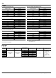
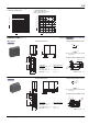
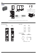
2. Specifications
* Specifications will vary with foreign standards certification ratings.
Notes:
*1. This value can change due to the switching frequency, environmental conditions, and desired reliability level, therefore it is recommended to check this with the actual load.
*2. Wave is standard shock voltage of 1.250s according to JEC-212-1981
*3. The upper limit of the ambient temperature is the maximum temperature that can satisfy the coil temperature rise value. Refer to “6. Usage, Storage and Transport
Conditions“ in AMBIENT ENVIRONMENT section in Relay Technical Information.
*4. The pick-up and drop out voltages rise approximately 0.4% for every 1C 33.8F given a standard ambient temperature of 20C 68F. Therefore, when using relays where
the ambient temperature is high, please take into consideration the rise in pick-up and drop out voltages and keep the coil applied voltage within the maximum applied
voltage.
REFERENCE DATA
Characteristics Item
Specifications
Standard type High capacity type
Contact
Contact material
1 Form A: AgSnO2 type
1 Form C, 2 Form A and 2 Form C: AgNi type
Arrangement 1 Form A, 1 Form C, 2 Form A and 2 Form C 1 Form A and 1 Form C
Contact resistance (Initial) Max. 100 m (By voltage drop 6 V DC 1A)
Rating
Nominal switching capacity (resistive load) 5A 250V AC, 5A 30V DC 10A 250V AC, 10A 30V DC
Max. switching power (resistive load) 1,250VA, 150W 2,500VA, 300W
Max. switching voltage 250V AC, 30V DC
Max. switching current 5A 10A
Min. switching capacity (reference value)*
1
100mA, 5V DC
Electrical
characteristics
Insulation resistance (Initial) Min. 1,000M (at 500V DC) Measurement at same location as “Breakdown voltage” section.
Breakdown voltage
(Initial)
Between open contacts 1,000 Vrms for 1 min. (Detection current: 10 mA)
Between contact and coil 5,000 Vrms for 1 min. (Detection current: 10 mA)
Between contact sets 3,000 Vrms for 1 min. (2 Form A, 2 Form C) (Detection current: 10 mA)
Temperature rise (coil)
1 Form A: Max. 45C 113F,
1 Form C, 2 Form A and 2 Form C:
Max. 55C 131F
(resistive method, with nominal coil voltage and
at nominal switching capacity, at 20C 68F)
1 Form A: Max. 45C 113F,
1 Form C: Max. 55C 131F
(resistive method, with nominal coil voltage and
at nominal switching capacity, at 20C 68F)
Surge breakdown voltage*
2
(Between contact and coil) (Initial)
10,000 V
Operate time (at nominal voltage) (at 20C 68F) Max. 15 ms (excluding contact bounce time.)
Release time (at nominal voltage) (at 20C 68F) Max. 5 ms (excluding contact bounce time) (Without diode)
Mechanical
characteristics
Shock resistance
Functional 98 m/s
2
(Half-wave pulse of sine wave: 11 ms; detection time: 10s.)
Destructive 980 m/s
2
(Half-wave pulse of sine wave: 6 ms.)
Vibration resistance
Functional 10 to 55 Hz at double amplitude of 1.6 mm (Detection time: 10s.)
Destructive 10 to 55 Hz at double amplitude of 2.0 mm
Expected life
Mechanical (at 180 times/min.) Min. 510
6
Electrical (at 6 times/min.) Min. 10
5
(at resistive load)
Conditions
Conditions for operation, transport and storage*
3
Ambient temperature*
4
: –40C to +60C –40F to 140F (Class E),
(Class B: –40C to +85C –40F to 185F)
Humidity: 5 to 85% R.H. (Not freezing and condensing at low temperature)
Max. operating speed
(at nominal switching capacity)
Flux-resistant type: 20 times/min., Sealed type: 6 times/min.
Unit weight Approx. 13 g .46 oz
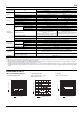
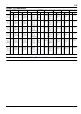
JW 1 Form A Standard (5A) type
1. Maximum operating power
2. Operate/release time
Sample: JW1aSN-DC12V-F, 10 pcs.
Ambient temperature: 20C 68F
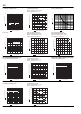
3. Life curve
1 Form A Standard (5 A) type
10
100
10 100 1,000
1
Contact voltage, V
AC resistive
load
DC resistive
load
Contact current, A
80 90 100 110 120
5
0
10
Min.
Max.
Min.
x
-
x
-
Max.
Coil applied voltage, %V
Operate/release time, ms
Operate time
Release time
100
10
51015
Contact current, A
Life, x 10
4
250 V AC resistive load
30 V DC resistive load